


OM2200A Remote control
ASK FOR SHIPPING TIMES
GENERAL DESCRIPTION:
Remote Control expands the possibilities of using OM2200A up to 10 meters away from your operating position. When needed, it is also possible to connect the Remote Control unit to the LAN network and control it using special software (not part of this package) for unlimited distance.
WARNING: It is absolutely a must to observe and follow all best practices and safety precautions, as well as local health and safety law and fire/electrical regulations. We recommend using visual remote control like a Web Camera etc.
The package includes:
- OM2200A Remote Control
- Power supply 230V / 12V, 600mA
- 10m patch lead to connect Remote Control with OM2200A PA
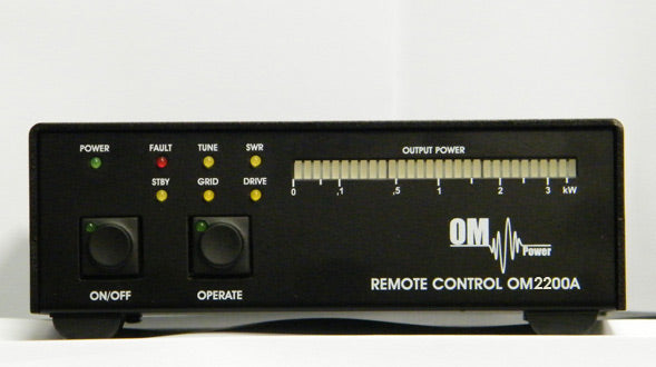
- ON / OFF: standard ON / OFF switch. Its state is indicated by a green LED on the switch;
- OPERATE: button controls the operating state of the PA. In operating mode, the green LED is lit;
- POWER: Power LED indicates the power supply connection. 12V / 500mA;
- FAULT: Red Fault LED error indicator PA. It is lit on any fault condition;
- STBY: yellow LED indicates the standby state of the PA;
- TUNE: yellow LED will light up if the PI tuning circuit indicates that additional tuning is necessary;
- GRID: indicates 2nd grid protection. Triggered if the safe screen current has been reached);
- SWR: Yellow LED will indicate excessive reflected power on PA’s antenna socket;
- DRIVE: will light up if the maximum drive power has been exceeded;
- POWER: 30 segments bar graph indicates peak output power;
- LAN: standard RJ45 connector - LAN Interface for remote access;
- ON: Main ON / OFF switch. (Cuts off 12V supply to unit);
- DC 12V: power jack (5.5 / x2.1) for 12V / 600 mA supply;
- CAL: calibration potentiometer (if necessary to synchronize the power bar graph with the bar graph on OM2200A);
- PA: socket for direct connection to OM2200A PA
WARNING: Please pay extra attention not to use the PA socket as a LAN socket as harmful voltages could damage your Ethernet devices such as switches, PCs, etc. Use only the supplied 10m cable to connect the PA with the remote control.
GROUNDING:
The remote control unit must be grounded properly! Connect the screw on the rear panel of the box to your local grounding system with a copper cable; use a cross-section of at least 4 mm2. Connect your transceiver and amplifier to the same grounding system of your shack carefully! If you use a power amplifier with higher output, you must be aware that your grounding system works properly. All parts must be grounded to the same system. Use short cables and make sure that there are good contacts! Otherwise, you run the risk of damaging your equipment, having problems with TVI/BCI, or your signal might be distorted.
DEPLOYMENT INSTRUCTIONS:
- Connect unit with OM 2200A PA using the supplied cable;
- Supply 12V DC voltage to the power socket using the supplied PSU;
- Check that the green POWER LED and the yellow STBY LED are both lit. Should any connection fault occur, it will be indicated by sequenced POWER and STBY flashing, and the FAULT LED will be lit constantly;
- Turn the PA on using the ON button. The tube heating process will begin. This will be indicated by the green LED on the ON button and by the flashing of the four LEDs (TUNE, GRID, SWR, DRIVE) (WAIT LED will also be lit on the PA’s front panel);
- After the heating process, the PA is now ready to be turned into operating mode using the OPERATE button. Use the same switch to enter STBY / OPERATE (works as a reset should a fault state occur);
LAN CONNECTION:
- The remote unit is interfaced to LAN via Xport made by Lantronix (type XP1001000-05R). More info can be found at: www.lantronix.com
- Default Xport settings are:
- IP address: 192.168.1.222 (first series can be: 192.168.1.101);
- Mask: 255.255.255.0;
- Gateway: 192.168.1.1;
You can modify any of these via the web browser. We do not recommend changing any other parameters of the EXPORT interface. Loss of communication can be caused precisely in this way. There is no default username or password. We strongly recommend securing the web interface with a username and password. For remote control and monitoring over LAN, special software is available free of charge and can be downloaded from the following address: https://www.om-power.com/download
General description of the OM 2200 A Remote control
Remote Control expands possibilities of using OM2200A up to 10 meters away from your operating position. When needed it is also possible to connect Remote Control unit to LAN network and control it using special software (not part of this package) to unlimited distance.
Warning: It is absolutely a must to observe and follow all best practices and safety precautions as well as your local health and safety law and fire / electricity regulations. We do recommend using visual remote control like Web Camera etc.
Package includes:
- Remote control OM2200A
- Power supply 230V / 12V, 600mA
- 10m patch lead to link Remote control with OM2200A PA
| Label | Description |
| ON / OFF | - Standard ON / OFF switch. On state is indicated by green LED on the switch |
| OPERATE | - button controls the operating state of the PA. When i noperating mode green LED is lid |
| POWER | - Power LED indicates connection of power supply. 12V / 500 mA |
| FAULT | - Red Fault LED indicates fault on PA. It shall be lid on any fault condition! |
| STBY | - yellow LED indicates Stadby state of the PA |
| TUNE | - yellow LED will be lid if PI tuning circuit indicates that additional tuning is necessary |
| GRID | - indicates 2nd grid protection. Trigered if safe screen current has been reached ) |
| SWR | - Yellow LED will indicate excessive reflected power on PA’s antenna socket |
| DRIVE | - will be lid if maximum drive power has been exceeded |
| OUTPUT POWER | - 30 segments bar graph will indicate peak output power |
| LAN | - Standard RJ45 connector - LAN Interface for remote access |
| ON | - Main ON / OFF switch. (Cut’s off 12V supply to unit) |
| DC 12V | - power jack (5,5 / 2,1) for supply of 12V / 600mA |
| CAL | - calibration potentiometer ( if necessary to synchronize the power bar graph with bar graph on OM2200A ) |
| PA | - socket for direct connection to OM2200A PA |
Warning: Please pay extra attention not to use PA socket as LAN socket as harmful voltages could damage your Ethernet devices such as switches, PCs etc. Use only supplied 10m cable to connect your PA with Remote Control unit.
Grounding
The Remote control box has to be grounded properly! Connect the screw on the rear panel of the box to your local grounding system with a copper-cable; use a cross-section of 4 mm2 at least. Connect your transceiver and amplifier to the same grounding system of your shack carefully! If you use a power amplifier with higher output you have to be aware that your grounding system works properly. All parts have to be grounded to the same system. Use short cables and make sure that there are good contacts! Otherwise you run the risk of damaging your equipment, having problems with TVI/BCI or your signal may be distorted.
Deployment instructions:
- Connect unit with OM 2200A PA using supplied cable
- Supply 12V DC voltage to power socket using supplied PSU
- Check that green POWER LED and yellow STBY LED are both lid. Shall any connection fault occur it will be indicated by sequenced POWER and STBY flashing and FAULT led will be lid constantly.
- Turn the PA on using the ON button. Tube heating process will begin. This will be indicated by green LED on the ON button and by flashing of four LEDs (TUNE,GRID,SWR,DRIVE) (WAIT led will be also lid on the PA’s front panel)
- After heating process PA is now ready to be turned into operating mode using OPERATE button. Use same switch to enter STBY / OPERATE (works as reset shall fault state occur)
LAN Connection
Remote unit is interfaced to LAN via XPORT made by Lantronix (type XP1001000-05R). More info can be found at www.lantronix.com
Default factory settings of XPORT are:
IP address: 192.168.1.222 (first series can be: 192.168.1.101)
Mask: 255.255.255.0
Gateway: 192.168.1.1
These are strictly default settings. You can modify any of these by going to XPORT web GUI via your web browser. We do not recommend changing any other parameters of the XPORT interface as loss of communication can be caused by doing so. There is no default user name or password. It is highly recommended to secure web interface with username and password.
For remote control and monitoring over LAN special software is needed. It is available free of charge; it can be downloaded from the following address:
https://www.om-power.com/download


