


Description
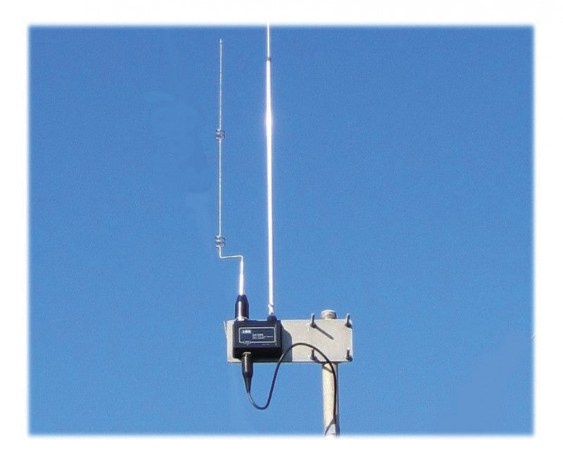
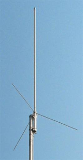
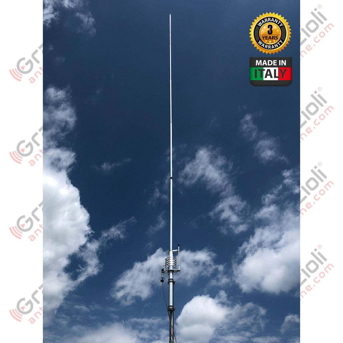
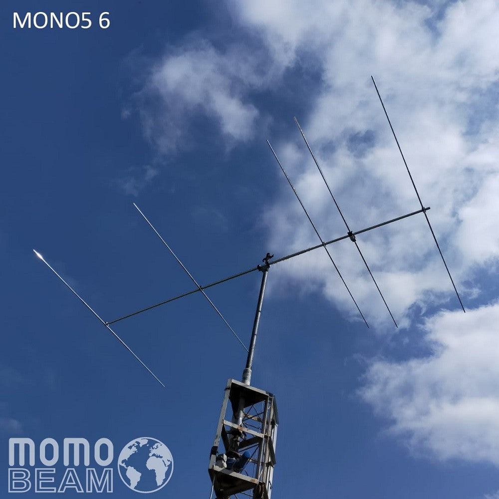
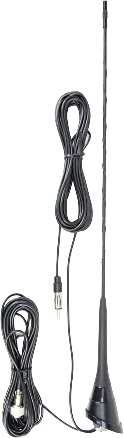
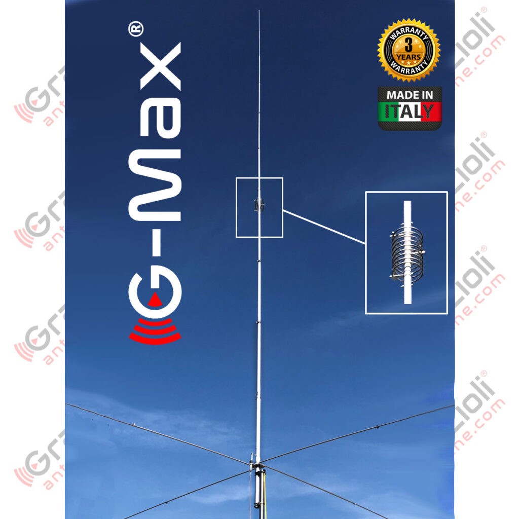
G-Max is the first and only vertical antenna in the world for 10 or 11m bands in a 5/8? over 1/4? collinear high-gain configuration.
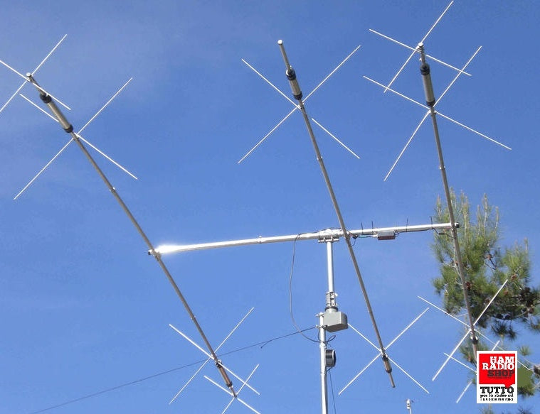
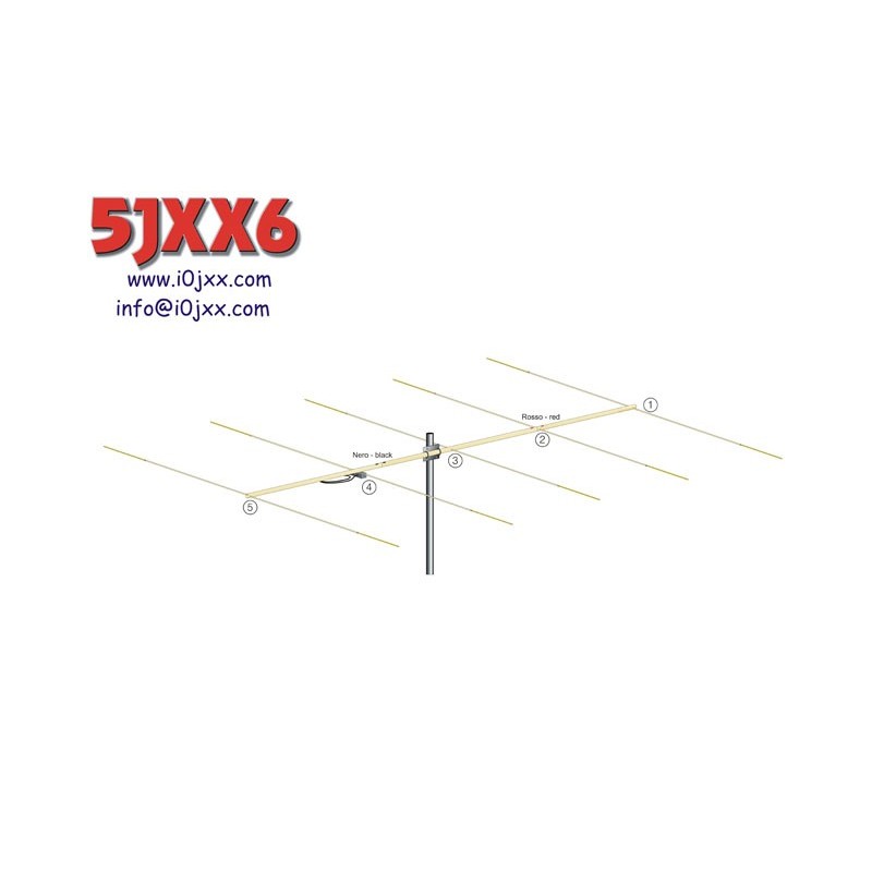
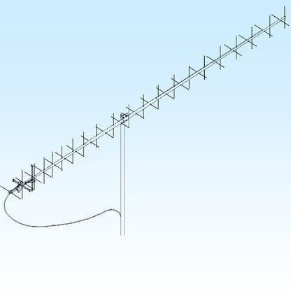
Built on the mechanics of the already proven FE10V, this antenna offers exceptional performance comparable to or superior to a 2-element Yagi, but with the advantage that G-Max is omnidirectional.
G-Max fears no comparison with any other vertical antenna on the market, whether 5/8, J-Pole, or other types available.
Thanks to its high gain and compressed main lobe with a low radiation angle, it will guarantee unprecedented performance.
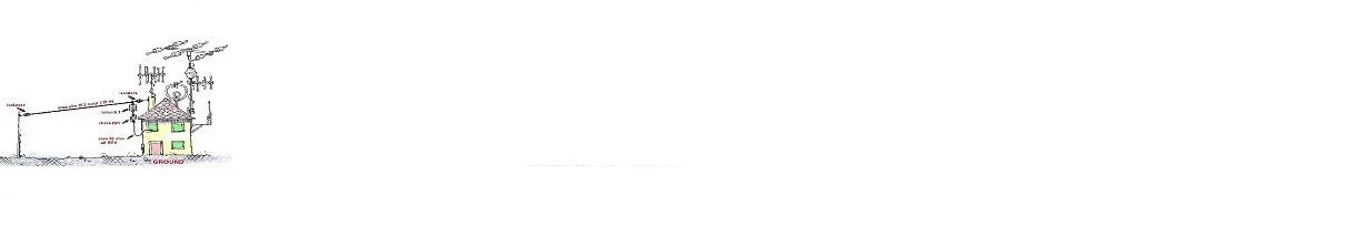
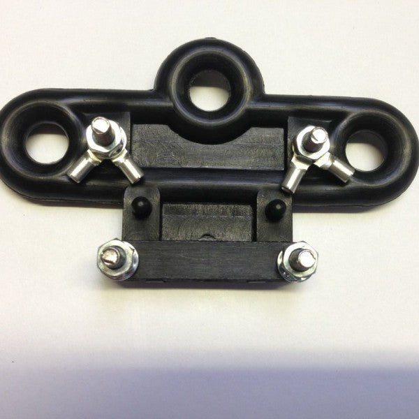
NOTE: Supplied with a 3-point guy wire plate, which we always recommend installing.

| Electrical Data | Mechanical Data | |||||
|---|---|---|---|---|---|---|
| Type | Collinear GP 5/8? over 1/4? in phase |
Materials | Cold-drawn tube in AW6063-T66 aluminum alloy, Fiberglass, Brass, PTFE. All screws in AISI-304 and 316 stainless steel | |||
| Frequency Range | Tunable from 27 to 28.5 MHz | Wind surface | 0.34m2 | |||
| Impedance | 50? Unbalanced | Load @ 130Km/h | 32.5Kgf | |||
| Radiation | Omnidirectional | Wind resistance (without ice) | 130 Km/h (guy-wired) | |||
| Polarization | Linear – Vertical | Overall Height | 10.85m at 27MHz | |||
| Gain | 3.5dBd – 5.65dBi | Radial Length | 2.7m (quarter wave) | |||
| Bandwidth with SWR 2:1 | = 1.3MHz @ 27MHz | Mounting pole | ø 40-54 mm | |||
| SWR at resonance | =1.2 measured at the connector | Net Weight | 6.8 Kg | |||
| Max input Power | 5000 Watts continuous in all emission modes | Packaging Dimensions | 14x14x145 cm | |||
| Feed System | Directly connected to DC ground | Weight in package | 8.2Kg | |||
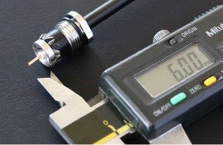
| Connector | Female UHF 50? with PTFE insulator, gold-plated center pin | |||||
For our tubes, we used the best material available for antenna construction; it is an Aluminum, Magnesium, and Silicon alloy called AW6063-T66, tempered to T-66 state. This gives the element exceptional strength, which is achieved by extrusion and then cold drawing.
Our tubular elements are extremely precise in both diameters and wall thickness, allowing for precise coupling with the least "play" between tubes.
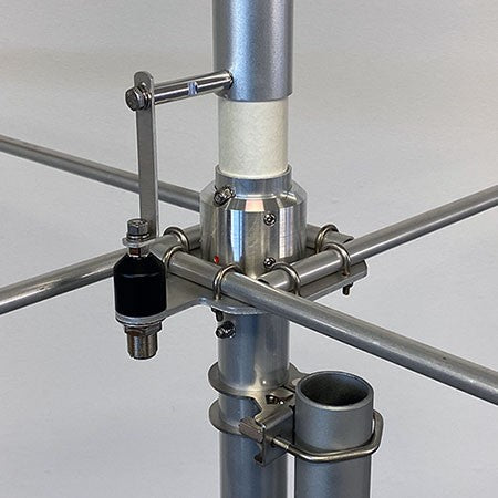
The "Ground Plane" consists of 4 robust 2.7m "Full-Quarter Wave" radials made of two telescopic sections with clamp fastening, with diameters and thicknesses of 13x1.25mm and 10x1mm respectively.
The radials are fixed to the support plate using two U-bolts and self-locking nuts; in the fastening area, 4 fiberglass reinforcements are provided to strengthen the joints and prevent crushing.
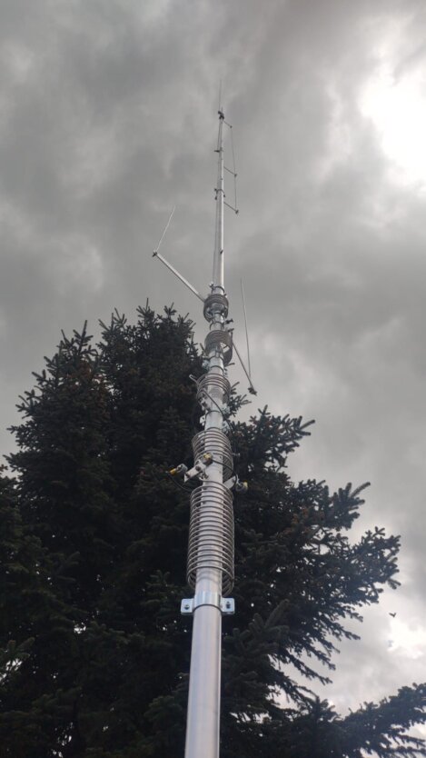
Grazioli "G-Max" is a high-gain collinear ground plane vertical antenna. The radiating element is made of two distinct sections fed in phase via a special aluminum coil appropriately positioned on the element.
The feed is direct and occurs at the bottom of the element, which has a length of approximately 1/4?, then, via the phasing coil, the RF signal also feeds the upper part, approximately 5/8? long, in phase.
The result is that the entire 10.3m element radiates in phase with a gain of almost 6dBi and a very low radiation angle (typically around 8°).
The Ground Plane is resonant with "Full Quarter Wave" radials that further enhance its performance and further reduce the radiation angle.
Built on the mechanics of the already proven FE10V, this antenna offers exceptional performance comparable to or superior to a 2-element Yagi, but with the advantage that G-Max is omnidirectional.
NOTE: Supplied with a 3-point guy wire plate, which we always recommend installing.
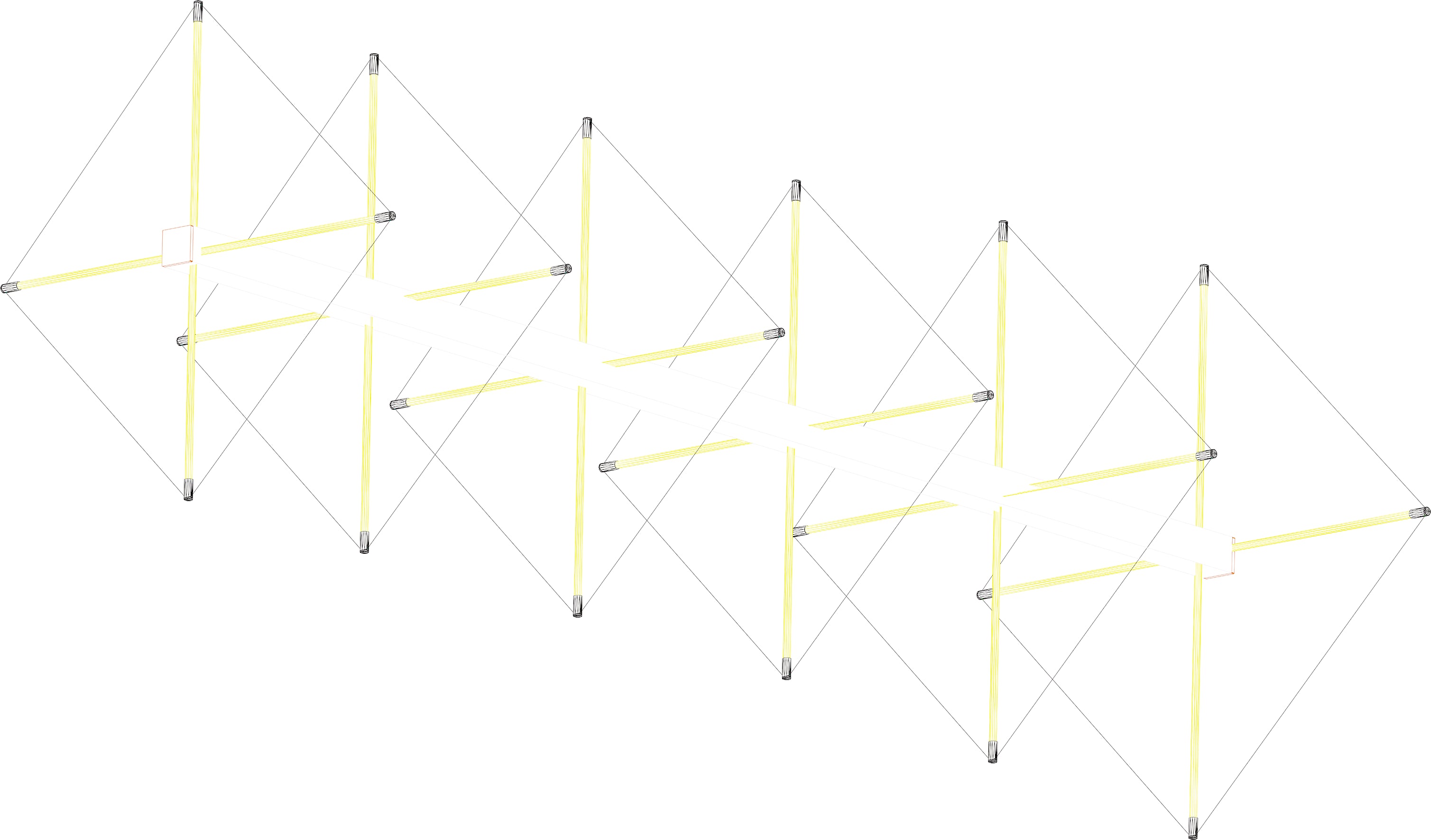
Diagrams


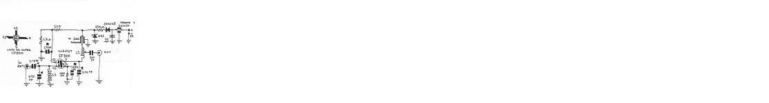
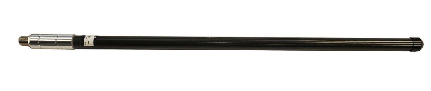
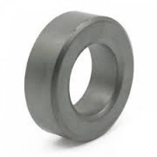
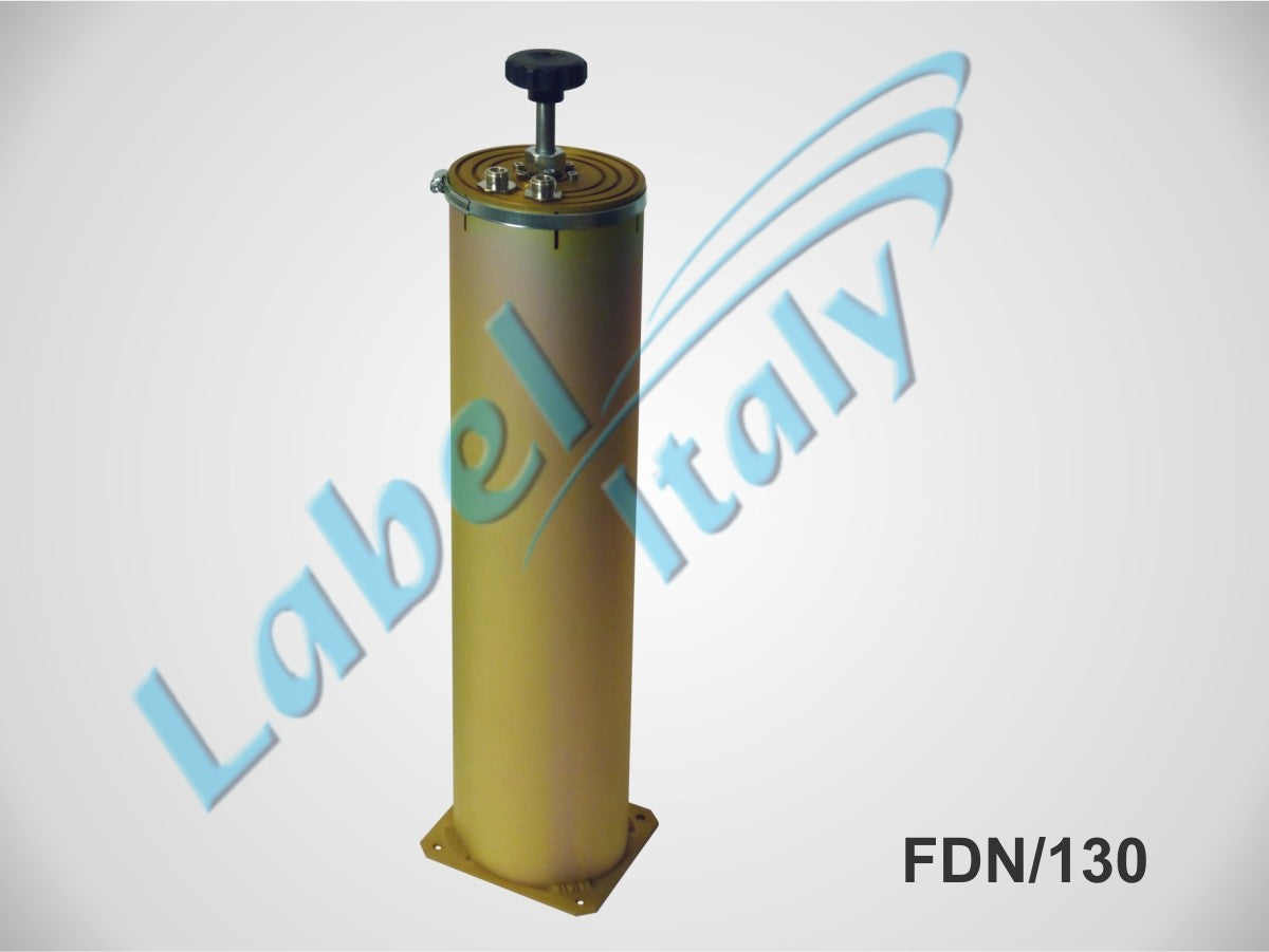
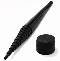
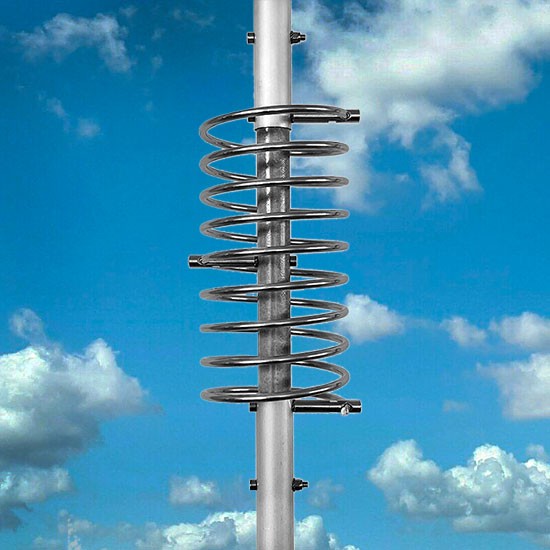
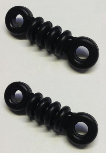
The Phasing Coil
The G-Max coil has been carefully positioned at the ends of the two central radiating sections.
It performs three extremely important functions for this type of collinear antenna. The first is to delay the RF signal phase by 180° between the first 1/4 Lambda section and the second 5/8 Lambda section, ensuring that the entire radiating part (element) radiates in phase.
The second function is to compensate for the strong capacitive reactance present on the upper 5/8 part with its intrinsic inductive reactance, and the third function is to transfer all input power to the upper part without losses.
All this is made possible thanks to the high "Q" factor of our coil, designed to best perform all three mentioned functions.

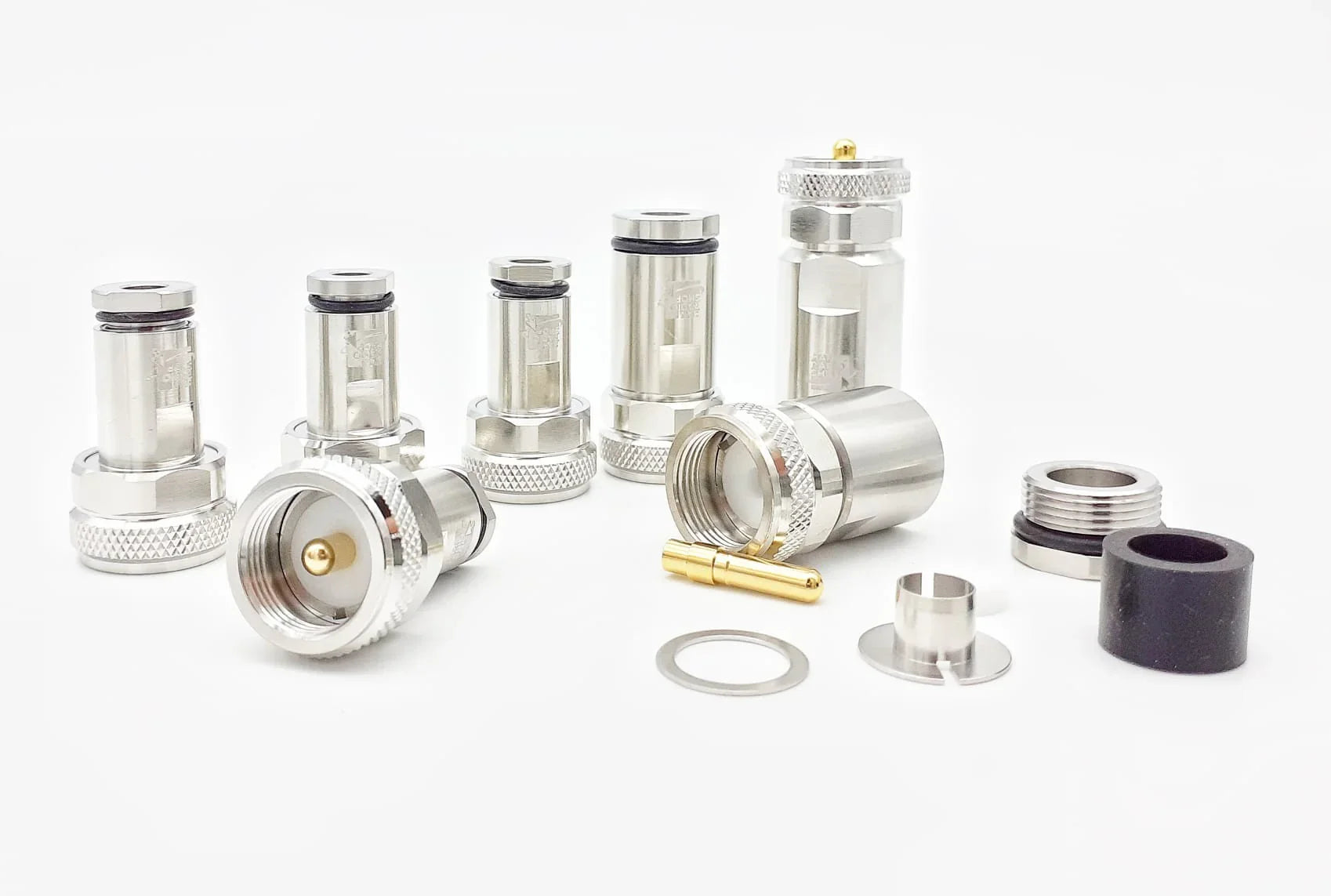
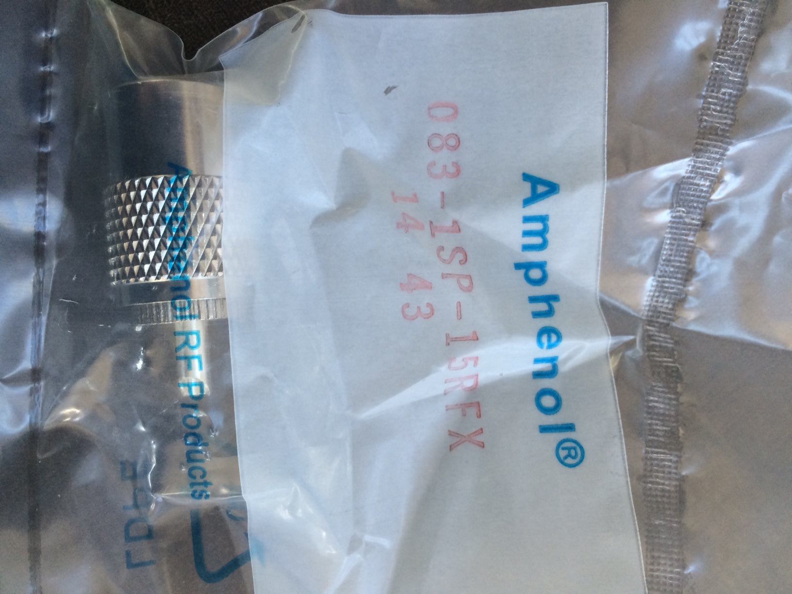
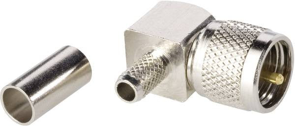
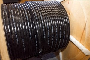
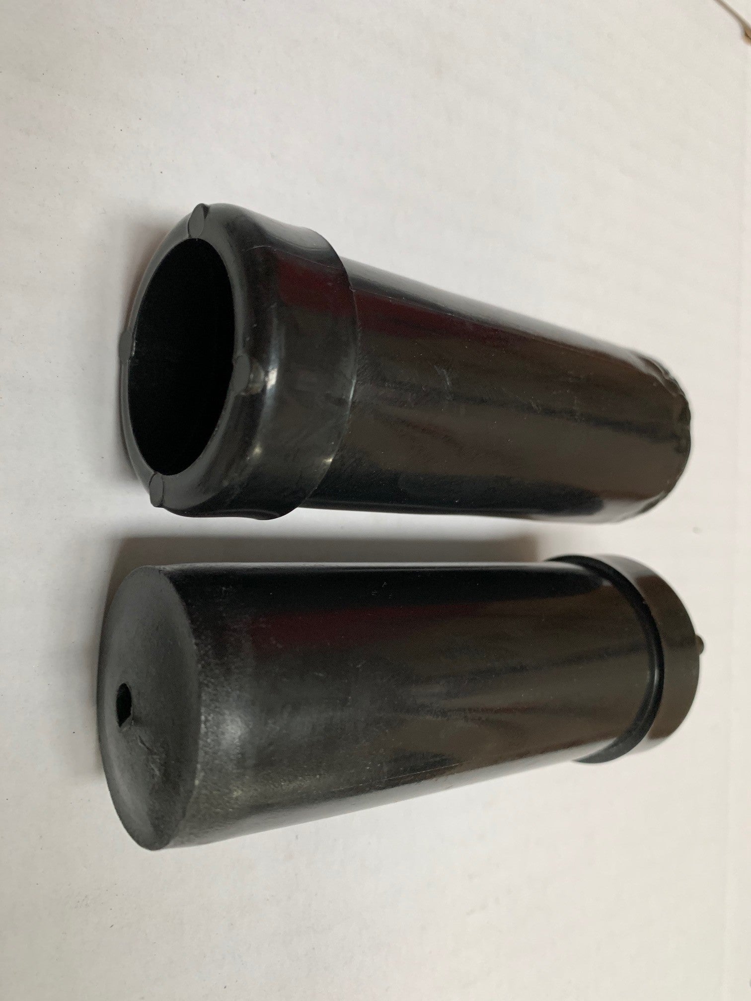
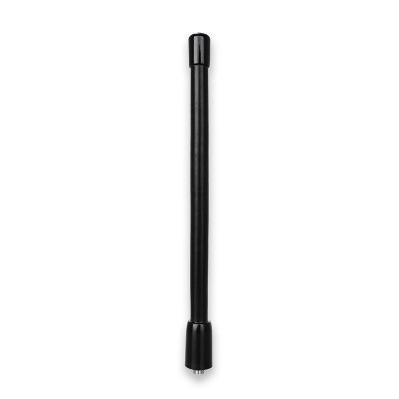
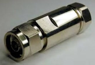
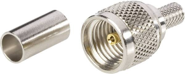
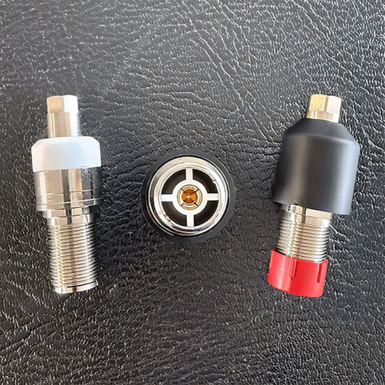
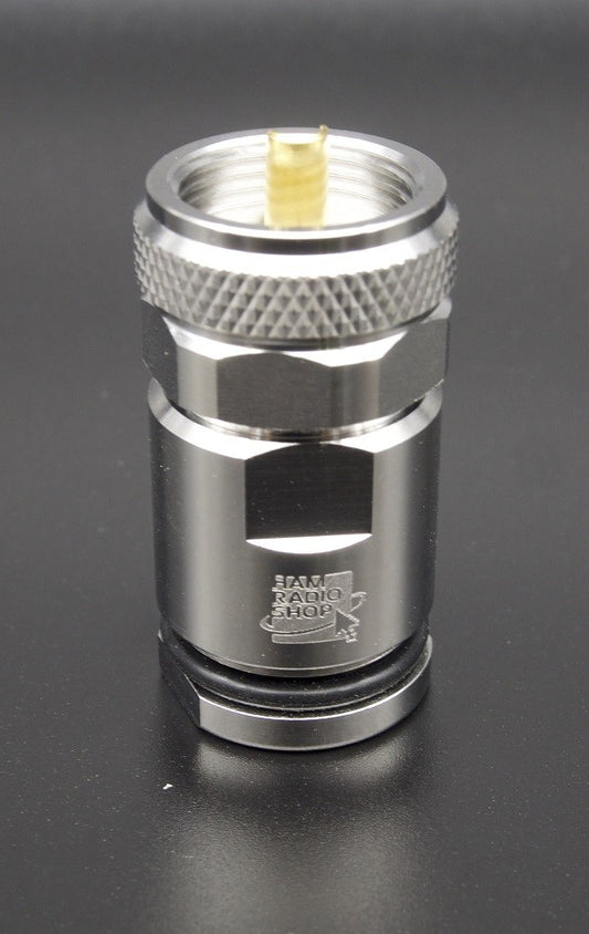
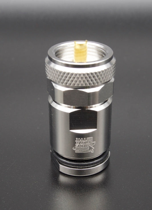
The UHF Connector
The G-Max connector is not a commercial SO-239 type as used by most manufacturers. The connector was designed and built directly by us, has a real impedance of 50 Ohm and can be used up to 500MHz. The goal was to create a reliable connector capable of handling 5Kw continuous CW at 30MHz.
The body is made of nickel-plated CW614N brass, while the pin is 24K gold-plated to prevent oxidation and features a 4-vane insulator that maintains its centering and elasticity, preventing loss of contact.
The insulating part is made of PTFE, one of the best insulating materials due to its exceptional electrical properties (low dielectric constant and reduced loss factor) and thermal properties (operating temperature from -100° to +260°). Finally, the connector is protected by a special elastomer cap that prevents water and humidity infiltration.

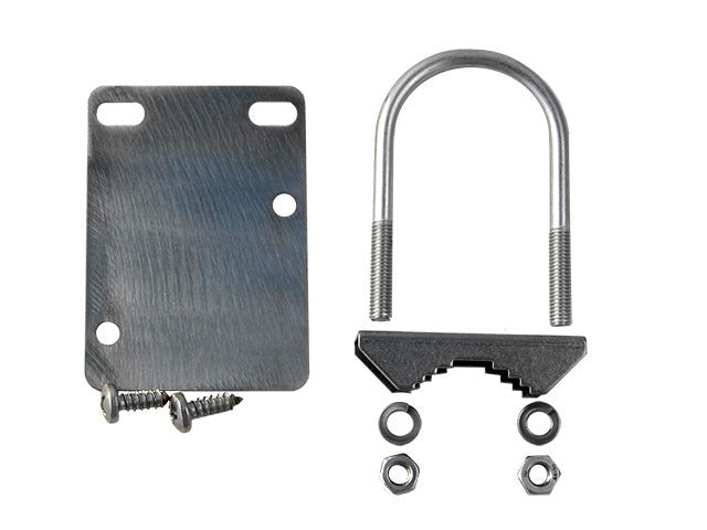
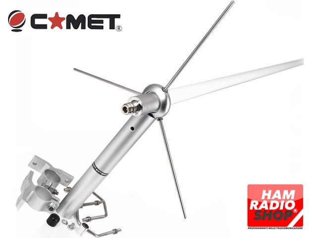
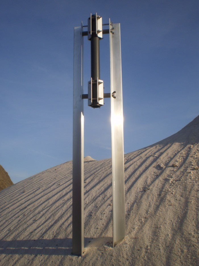
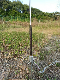
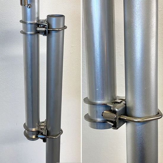
The Mounting Bracket
Made of 2.5 mm thick AISI304 stainless steel, it is attached to the antenna tube by a clamp system, creating an extremely robust mechanical lock.
The attachment to the mast is made with AISI304 M6 V-bolts and column nuts to facilitate tightening.


