
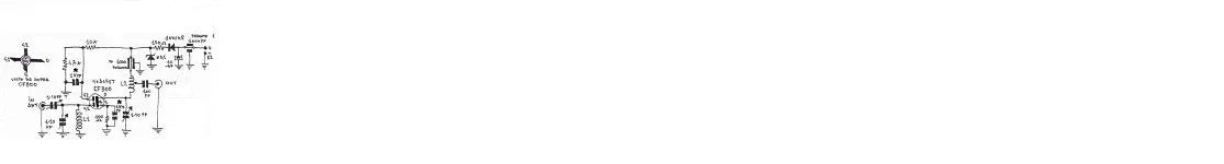


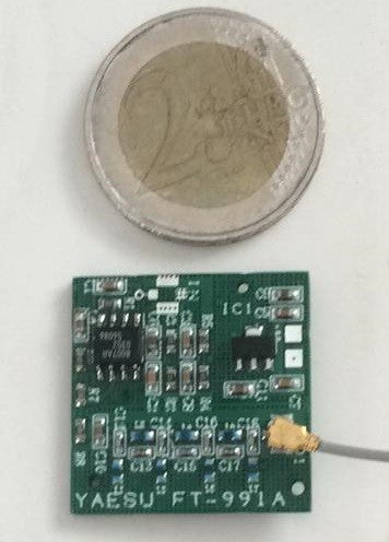


DDS Signal Generator 0-55MHz based on AD9850
Supports 0 ~ 55MHz continuous adjustment in 1Hz steps.
This generator has a 78L05 voltage regulator.
-
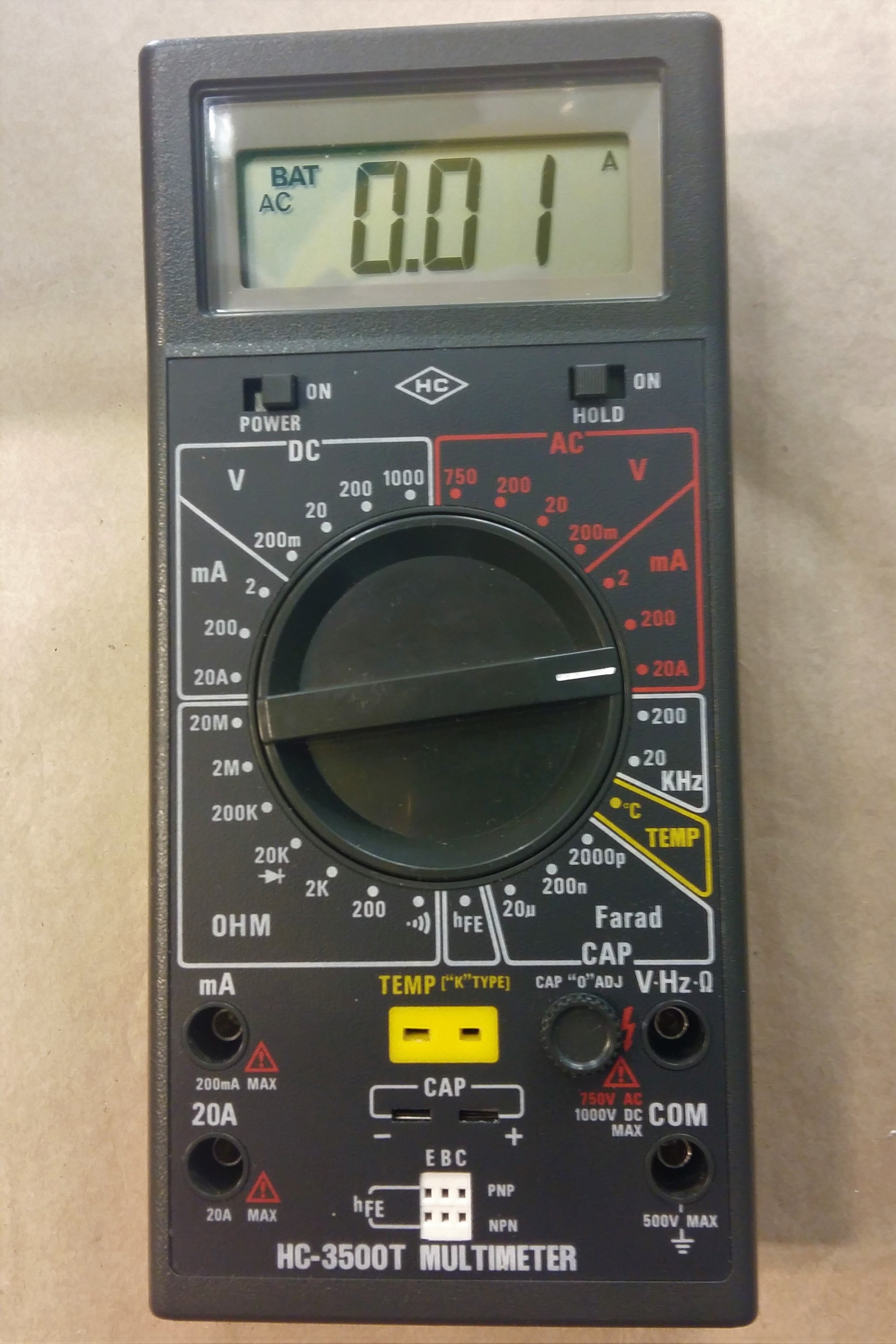
Input current at 200mA, an input voltage of 8-9V would be the ideal voltage.
5p/6p connect the encoder as shown in the photo.
(8V GND) is the 8V power supply from the main board. If powered by the main board, DDS does not need an independent power supply.
1 ~ 6 correspond to 6 frequency bands: (3.8,7, 9,14,18 or 21,27 or 29)
LSB, USB, CW are the three selected modes.
-
DT is signal from the main board.
Keys and connection interfaces:
ENC: encoder switch
MEM: switch for memory mode
VFO: Transfer from VFO A to VFO B or from VFO B to VFO A.
SSB: change of working mode: circular from USB, LSB, AM, CW, and so on ...
RIT: fine tuning of reception frequency
CAL: set functions
-
KB-1 and KB-2 have shared common pin, but it's not GND.
INSTRUCTION MANUAL DOWNLOADABLE BY CLICKING ON THE "ATTACHED DOCUMENTS" TAB OF THIS LISTING


