


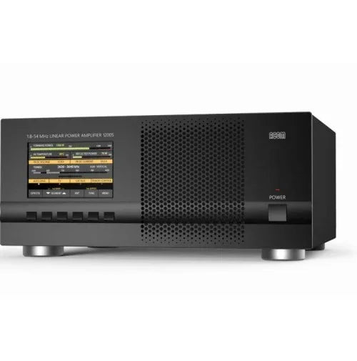


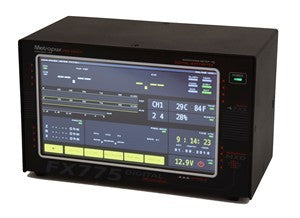


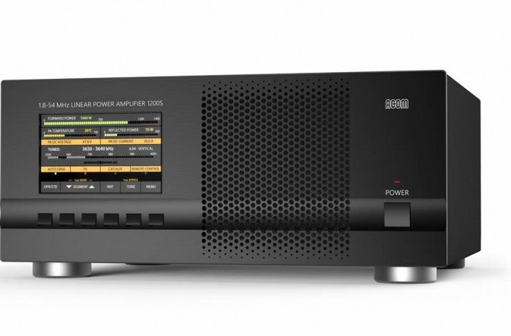
5-inch (5") (108x65mm) high-resolution, 800x480 pixel, 24-bit color display.
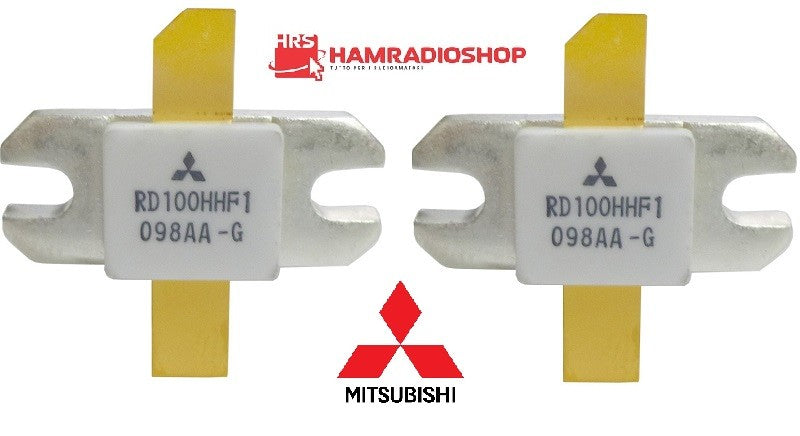
The final stage uses BLF188 type field-effect transistors (MOSFETs) from NXP, designed to withstand high output discrepancy (SWR) and intended for operation in aerospace, industrial, mobile, and broadcasting applications.
Compatible with all transceiver models available on the market - no special signals required: only "ground to transmit" (PTT) and 50 W RF drive power are needed.
Broadband input circuit providing a perfect transceiver load with SWR below 1.2:1 (typically 1.1:1), without retuning over the entire frequency range from 1.8 to 54 MHz.
The overall operation of the ACOM 1200S is extremely simplified: the on-screen menus are intuitive and easy to follow, and no special operator expertise is required when changing frequency bands.
Automatic control capability - when connected to a transceiver with a CAT interface, the amplifier constantly monitors, duly follows the operating frequency, and changes bands accordingly.
Even when not connected to the CAT interface, the amplifier monitors the input signal frequency through the built-in frequency counter and automatically switches bands.
Remote controlled via the RS232 interface.
It takes care of itself during operation thanks to continuously operating protection circuits in all modes.
The operator can digitally monitor more than 10 parameters concerning the amplifier's operating regime.
Easy maintenance: detailed data (55 parameters) related to each of the last 28 serious fault protection interventions are stored in the amplifier's non-volatile memory.
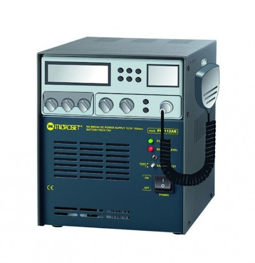
Convenient for expeditions and field operations: extremely compact and lightweight construction, extended mains voltage range (93 V ÷ 265 V), limited peak current, and purely sinusoidal consumed power supply current, automatic power factor correction (PFC) - all significant parameters when operating from unstable mains, generators, etc. features achieved thanks to the integrated switching mode power supply (SMPS).
Perfect electromagnetic compatibility (EMC) with both highly sensitive and powerful radio station equipment (receivers, computers, multiple amplifiers) exceeding standard EMC requirements thanks to the use of PFC and additional integrated radio frequency filters.
SPECIFICATIONS:
a) Rated output power: 1000 W +/- 0.5 dB, PEP or continuous carrier (1200 W typically).
b) Intermodulation distortions (IMD3): better than 30 dB below the nominal PEP output.
c) Suppression of harmonic and spurious emissions: better than 60 dB (65 dB typically).
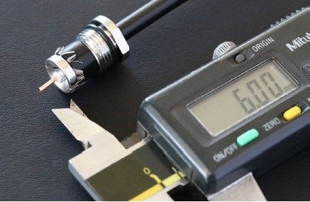
d) Input and output impedances: nominal value: 50 Ohm unbalanced, UHF type connectors (SO239);
• input circuit: broadband, SWR below 1.2:1 (1.1:1 typically); Continuous range from 1.8 - 54 MHz without retuning or switching;
• SWR RF bypass path - below 1.1:1, 1.8-54 MHz;
• Admissible SWR at the output load (antenna): up to 3:1 with proportional power reduction and up to 1.5:1 for full output power;
e) RF power gain: 13 dB +/- 1 dB;
f) Mains supply voltage: 93V?265V without switching;
g) Power consumption at maximum output power: 2000 VA or less with a power factor of 0.95 or higher;
h) Current consumption in low power mode (standby): less than 1VA;
i) Complies with EU safety and EMC standards, as well as US Federal Communications Commission (FCC) regulations;
j) Environmental working conditions:
• temperature range: -10 C to +40 C (14 F to 104 F);
• relative air humidity: up to 95% at 35 C (95 F);
k) Dimensions (excluding protrusions) and weight, in operation: (D x W x H) 418 x 372 x 162 mm (16.46 x 14.65 x 6.38 In); 14.5 kg (31.97 lbs).


