


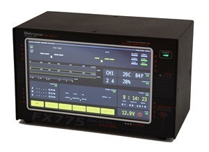


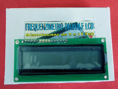
Programmable LCD Digital Frequency Counter 0.1 - 60 MHz
This is a 60 MHz frequency meter/counter for measuring frequency from 10 Hz to 60 MHz with 10 Hz resolution. The meter provides very stable readings and has excellent input sensitivity thanks to the on-board amplifier and TTL converter, so it can even measure weak signals from crystal oscillators. With the addition of a prescaler, it is possible to measure frequencies of 1GHz and above.
The basic idea comes from the Microchip AN592 application note: "Frequency counter using PIC16C5x" where you can find simple software that implements a frequency counter using a PIC microcontroller. I wrote specifically designed software to improve counter resolution, to handle the IF mode and value using an operating menu, to decode and edit the read frequency on an LCD display. The result was a simple and effective device.
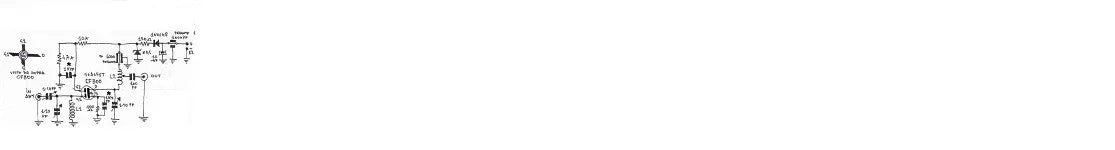
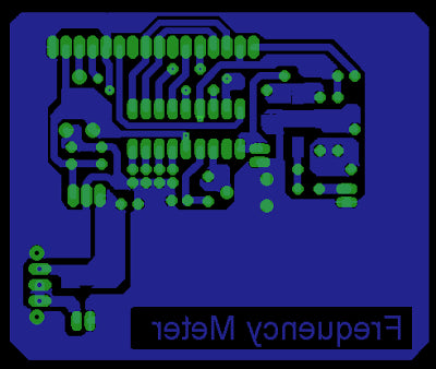
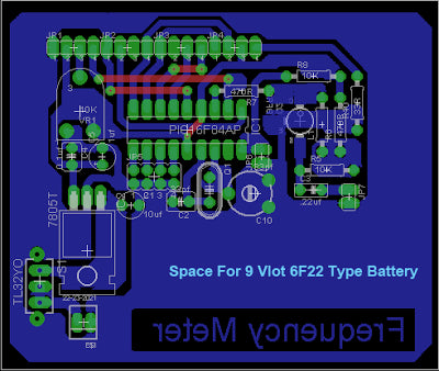
Circuit / Schematic
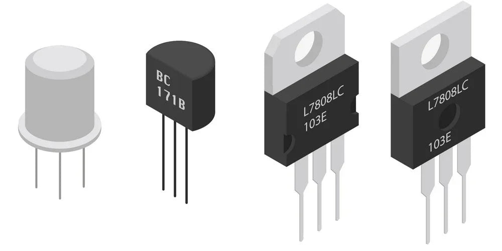
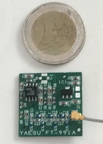
The electrical schematic is very simple, given that most of the functions are implemented by the microprocessor. Only an amplifier stage was needed to raise the input signal level from 200-300 mV p.p. to about 3 volts p.p. A self-biased common emitter amplifier produces a pseudo-TTL driving signal. The 10uH inductor in the collector lead helps extend the high frequency response. Any "fast" NPN transistor should be suitable. I used a BFR91, but you may substitute a transistor salvaged from an old TV tuner or a VHF receiver.
The amplifier's quiescent Vce is set to 1.8 to 2.2 volts by the resistor marked * on the diagram. It is nominally 10K, but you may need to change it. The collector voltage is applied to the PIC's counter/timer via a series 470 ohm resistor. The PIC is able to short this signal to ground via an internal pull-down transistor to disable counting
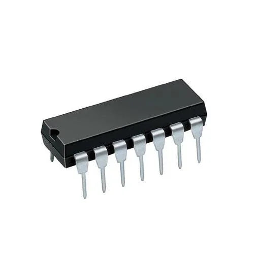
The PIC implements a 32-bit counter, partly in internal hardware and partly in software. Counting is enabled by turning off the internal pull-down transistor for "exactly" 0.4 seconds. At the end of this time, the PIC divides the count by 4, then adds or subtracts the appropriate IF frequency to get the actual frequency. The resulting count is converted to printable characters and delivered
to the display.
Calibration: before use
Before the frequency meter will work properly, it must be calibrated. This may be as simple as connecting a known frequency source and adjusting the trimmer capacitor so the correct value is displayed. If you are unable to adjust the displayed frequency, then a "coarse calibration" is required. This involves starting with the power off. Pin 10 is connected to ground and the power is then turned on (and held on). The PIC will measure and display the input frequency, followed by the letters CAL. If you can't adjust the indicated frequency to the correct value (by adjusting the 33 pF trimmer), then coarse adjustments can be made by briefly connecting pin 12 or pin 13 to ground. It may take several tries, because the program only checks these pins once each measurement (0.4 second). Once you are happy with the adjustment, remove the ground from pin 10 (while power is still applied). This will cause the PIC to store the calibration in non-volatile internal memory.


