

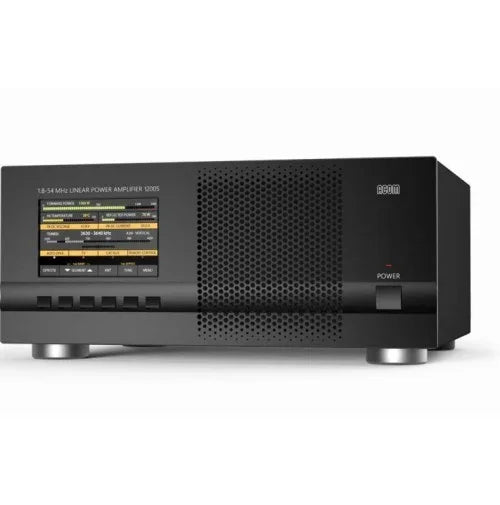


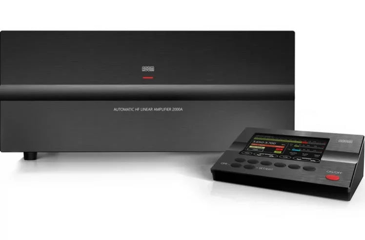
The ACOM 2000A represents a major advance in the state-of-the-art in HF amplifier design. It forever changes the way radio amateurs use HF power amplifiers in their stations.
Instant, automatic tuning makes slow, cumbersome band changes a thing of the past.
A new standard of amplifier features and performance: A built-in, wide-range antenna tuner matches loads with high VSWR (up to 3:1), often eliminating the cost and complexity of an external, high-power antenna tuner.
RS-232 digital control allows full integration into any computer-driven station setup. Advanced protection circuitry ensures amplifier safety under every potential combination of operating conditions. Remote diagnostic capabilities and modular design ease fault isolation and repair.
Cutting-edge technology enhances a classic design
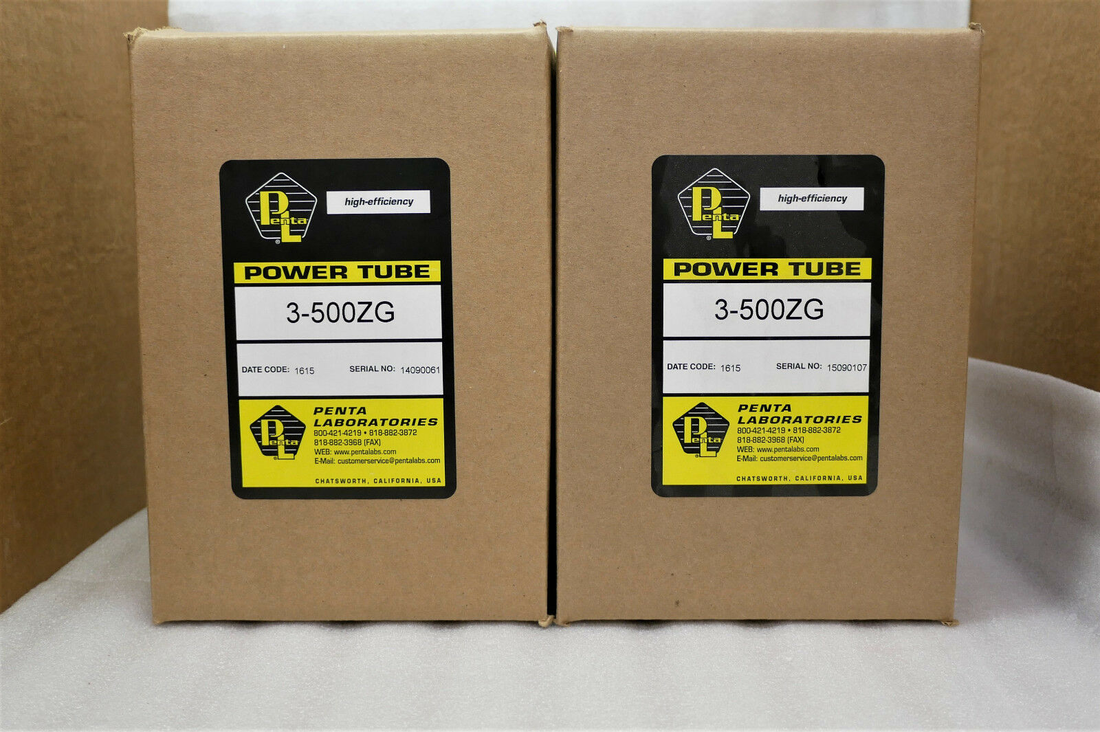
At the heart of the ACOM 2000A is a classic HF amplifier design, employing two Svetlana 4CX800A (GU74B) high-performance metal-ceramic tetrodes operating in a grid-driven configuration. This design was chosen for its inherent stability and extremely low spurious emission output. ACOM coupled this proven-and-true configuration with today's most advanced digital control technology to create an amplifier with outstanding performance, features, and reliability.
Signal: excellent transceiver load (typically below 1.2:1 input VSWR), and regulated screen grid voltage result in an extremely low distorted output. Measured typical IMD are - 40dB (3rd order) and - 45dB (5th order). Classic Pi-L network, all air coils (no ferrite), and careful design layout of the output tank provide typical harmonic emissions as low as - 55dBc (second) and below - 70dBc (third and above). Thus, chance of QRM, BCI or TVI is dramatically minimized.
Fully Automatic Tuning
The automatic tuning features in the ACOM 2000A represent a true breakthrough in HF amplifier design. Never again think about an ATU for VSWR up to 3:1 (2:1 on 160m). Matching the actual antenna impedances to the optimal tubes load is fully automated. Typically 1 second and no skill is required. By completely eliminating time-consuming tuning procedures, the ACOM 2000A gives contesters a real edge. You can now change bands without a moment's hesitation. You can work every multiplier spotted using point-and-shoot software — regardless of band. And you always know the amplifier is properly tuned and operating safely. The amplifier follows the transceiver's band and frequency automatically in less than a second. No special cables are needed. Just a dot on CW or "Ah" in SSB are enough. The ACOM 2000A breaks each amateur band into frequency segments. The user can store up to ten (10) sets of tuning adjustments for all frequency segments — allowing individual settings for multiple antennas on each band. VSWR can rise considerably when an antenna is operated away from its resonant frequency. Unlike other amplifiers on the market today, the ACOM 2000 output matching network allows the amplifier to operate at full power, even with VSWR as high as 3:1 (2:1 on 160m).
Advanced Digital Control: Microprocessor control improves performance and makes possible a wide range of new advanced features.
QSK
Full break-in (QSK) based on a built-in vacuum relay. Transmit/receive switching sequence is guaranteed by a dedicated microprocessor.
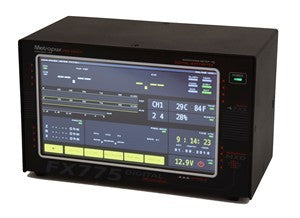
Remote Control Unit: RCU Dimensions: 167 x 130 x 25 mm (6-2/3" x 5-1/8" x 1").
Only the remote control needs to be placed near the operator. The main unit can be installed up to 3 meters (10 feet) away. RCU features include: amplifier status displayed on the LCD, control of all functions, measurement and/or monitoring of 20 most important parameters, on-board technical assistance, troubleshooting tips, power-on hours record, password provided.
Easy Maintenance
The protection system makes damaging the amplifier a difficult job. Information about the 12 most recent protection trips is stored in an INFO BOX for remote diagnostics via telephone line, PC, and Internet.
RS232 and Networking: All functions are accessible from a PC via RS232 serial port. Local network may include more than one amplifier working/antenna unit set in a system.
Protection
All tubes voltages and currents, power supply voltages, overheating, overdrive, insufficient cooling airflow, internal and external RF arcs (in the amplifier, antenna selector, tuner or the antennas), T/R sequencing, hot switching antenna relay contacts, antenna matching quality, reflected power, stored data, power-on inrush current and interlock for operator safety. Antenna matching can be performed in less than 10 seconds and at one quarter of the rated power, which produces less chance of interfering with other stations and greater safety to amplifier components.
TECHNICAL SPECIFICATIONS:
- RF Output: 1500-2000W coded carrier or SSB - no time limit. 1500W RF output constant carrier mode - no time limit with auxiliary cooling fan.
- Frequency Coverage: All amateur bands 1.8-24.5 MHz. 28 Mhz only with modification by authorized amateur.
- Bandchange / Tuneup: Initial matching process to output in less than 3 seconds (typically 0.5 seconds). Preset matching process / bandchange takes less than 0.2 seconds to switch to different segment, same band and less than 1 second for QSY to different band.
- Tuning Memories: Non-volatile for up to 10 antennas per frequency segment.
- Drive Power: Typically 50W for 1500W output.
- Input Impedance: 50 ohms nominal. VSWR <1.5:1.
- Power Tolerance: Up to 3:1 VSWR (2:1 on 160m) at full rated power before SWR protection circuit activates. Higher SWR tolerated at reduced output.
- Harmonics: At least 50 dB below peak output at 1500W.
- Intermodulation: At least 35 dB below peak output at 1500W.
- T/R and keying: Vacuum Relay: QSK capable.
- Tubes and Circuit: 4CX800A/GU74B tetrodes (2); resistive grid, PI-L output with negative RF feedback. Regulated screen grid voltage.
- ALC: Negative going, grid derived, -11v max, rear panel adjustable.
- Measurement: Comprehensive. Remote control unit allows flexible monitoring of all amplifier operating parameters.
- Protection: Grid and screen current limiting, power-on inrush (soft-start provided), trip on excessive reflected power, RF arcs, password protection if needed, proper T/R sequencing, tube exhaust overheating, cover interlock and HV power
disconnect.
- Fault Diagnosis: Remote control display and multiple "INFO Box" LEDs for 12 most recent events. PC interface (RS-232) plus remote telephone line interrogation capabilities.
- Cooling: Full cabinet forced air. Rubber isolated blower.
- Transformer: 3.5kVA with UNISIL-H strip-wound core.
- AC Power Requirements: 100/120/200/220/240 VAC nominal. 50-60 Hz. 3500VA single phase at full output.
- Physical: RF Unit: 17-1/4" W x 7" H x 17-3/4" D
- (440W x 180H x 450D mm).
- RCU: 5-1/4" W x 6-3/4" D x 1" H
- (135W x 25H x 170D mm).
- Shipped in two cartons total weight (96 lbs / 42.5kg). Detachable transformer for ease of installation and shipping.
- No Controls on the RF unit except for ON/OFF. RF unit can be located up to 3 meters (20m with optional cable) from the remote control.


