


.png)
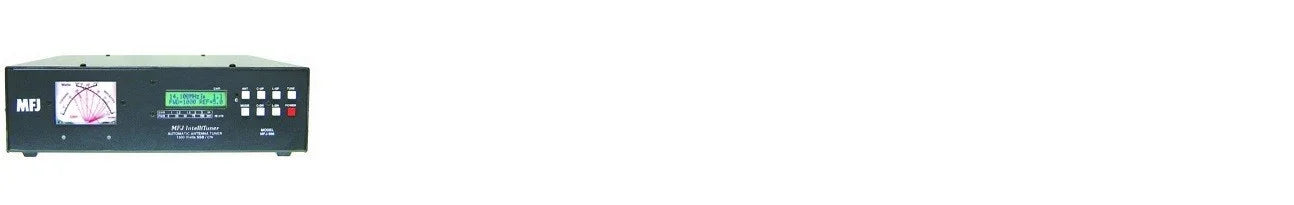
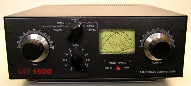
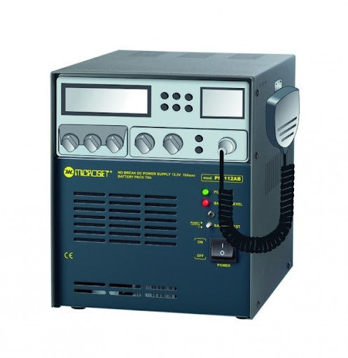
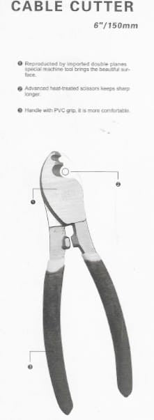
Rotator Control Unit 1216L
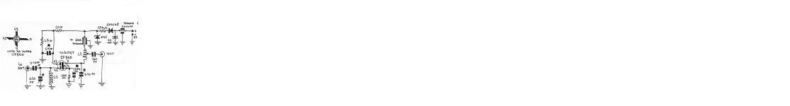
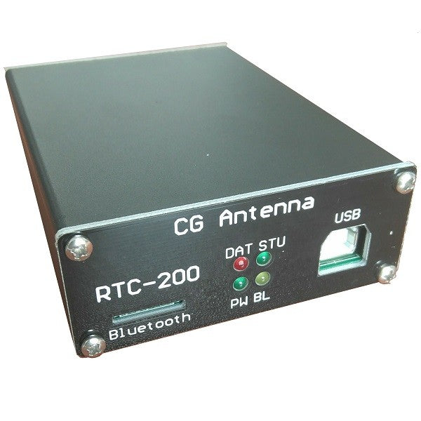
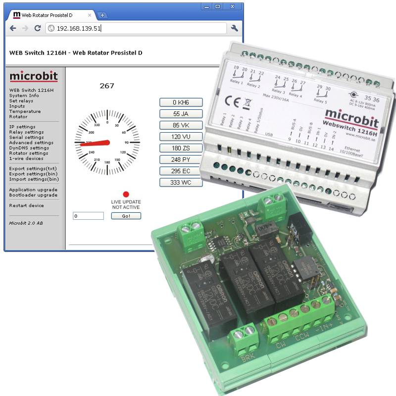
To create a web-based rotator control system, the Rotator Control Unit (RCU) is connected to the Webswitch 1216H. The remote control unit is connected via the 1-wire bus to the webswitch. The remote control unit has three 16A relays for clockwise and counter-clockwise rotation and for brake control. For azimuth (direction) reading, there is an A/D input that handles 0-7.5V or 0-15V. The A/D input is fully isolated. The remote control unit can be connected to most currently available rotator and rotating tower controls. The indicator can be calibrated every 30 degrees to handle non-linear potentiometers.
When using the Webswitch and the remote control unit, it is not necessary to use the RRC-serial ports for rotator control.
To create a web based rotator control the Rotator control Unit (RCU) is connected to the Webswitch 1216H. The RCU is connected via the 1-wire bus to the webswitch. The RCU has three 16A relays for CW and CCW rotation and for brake control. For the the azimuth (direction) reading there is A/D input which handles 0-7,5V or 0-15V. The A/D input is fully issolated. The RCU can be connected to most of the current available rotators and rotating tower controls. The indicatior can be calibrated every 30 degrees to handle potentiometers which is not linear.
When using the Webswitch and the RCU you do not need to use the RRC-serial ports for rotator control.
Installation
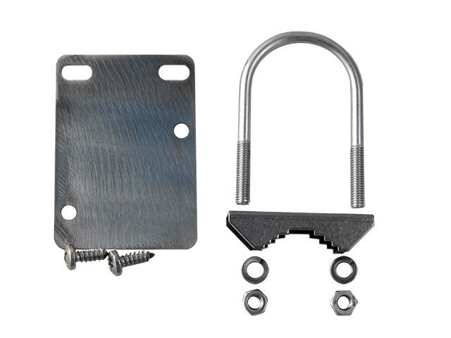
The Rotor Control Unit 1216L (RCU) is connected between the Webswitch 1216H and the Rotator Control box.
The RCU needs 12V power, an easy way is to connect it in parallell with the power to the Webswitch. Note! If you connect 12V to the Webswitch via the circular 2.1/5.5 mm DC-connector, + must be in the center.
The RCU gets it’s control signal trough the 1-wire bus from the Webswitch, either Bus A or B can be used, we use Bus B in the example above.
The relays are connected in parallell with the switches on the ordinary control box. The relays can handle <20VDC/16A, <30VDC/10A or 230VAC/16A
The Pot (A/D) input is connected in way that it will sense a Voltage between 0-15V depending on the direction of the Antenna.
There are calibrations points at every 30 degrees so the input volatage do not have to be 100% linear.
The input Inpedance is >220K so it can be connected almost everywhere. The Pot Input is fully issolated from Ground.
Attention! If you connect the RCU to a HAM or CDE rotator remember that the break relase button is connected on the primary side of the transformer.
The RCU handles 230V but you have to be careful when doing the installation, keep to protection cover on the back of the PCB and mount the RCU inside the Rotator Control Box.

Set Up
Before you can use the Rotator control unit 1216L, there is a few steps which have to be done. First do the hardware installation, after that do the following.
Browse to the Webswitch 1216H, and select the “Rotator Settings” link at the menu to the left.
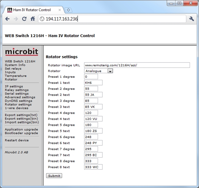
Set rotator to “Analogue” and press the “Submit” button.
Later on you can program the Presets here, I think it’s quite intuitive.
Then select the 1-wire link at the menu to the left.
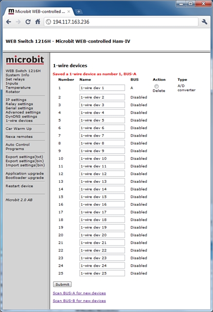
Then press “Scan BUS-A or B for new devices” depending on which bus you have connected the RCU 1216L to.
If everything is OK the Webswitch will indicate that it has found a A/D converter eg the RCU 1216L.
You can now change the name to something which is easier to recognize, for example Rotator.
The press the “Submit” button.

Now select the “Rotator” link at the menu to the left.
Then press the “Settings” link.
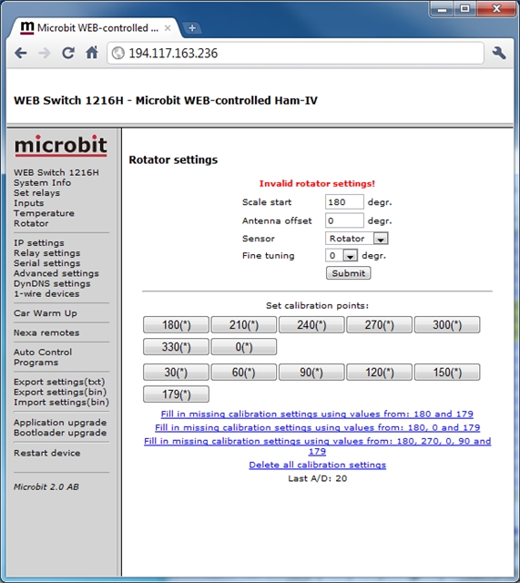
You will now see the Rotator settings window.
Enter “Scale start” value, If your indicator scale starts from 0 set 0, if it’s 180 set 180.
If your antenna is not mounted exactly accordning to the indicator you can set an “Antenna Offset” value.
In the sensor field select the sensor you scanned and renamed before, in this case “Rotator”.
The “Fine tuning” can be used if the antenna will go to short or to long when used fixed values, leave it at 0.
Press “submit” button.
From your ordinary Rotator control box turn the antenna fully Counter Clock Wise (CCW).
Press the first button “0″ or “180″ ( depending on where your scale starts) to learn the RCU A/D value indicating antenna fully CCW.
From your ordinary Rotator control box turn the antenna fully Clock Wise (CW).
The A/D value on the bottom of the page will Increase or decrease now.
When its fully CW, press the last button “360″ or “180″ ( depending on where your scale starts) to learn the RCU A/D value indicating antenna fully CW.
Then click on the link on the top “Fill in missing calibration settings………”
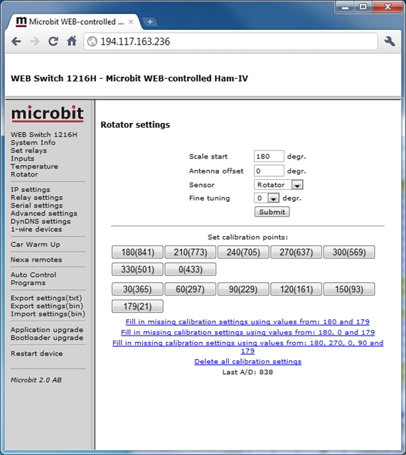
If your rotor indictor potentiometer is linear the settings are done now.
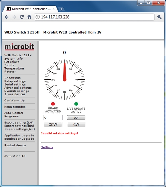
Now select the “Rotator” link at the menu to the left again.
Now test to rotate the antenna with the ordinary control box and compare the direction on the control box and the “Web” values.
If they follow each other the Potentiometer in the rotor is fairly linear an everything is OK.
If the pot is not linear you can set the values manually buy pressing the calibration points buttons.
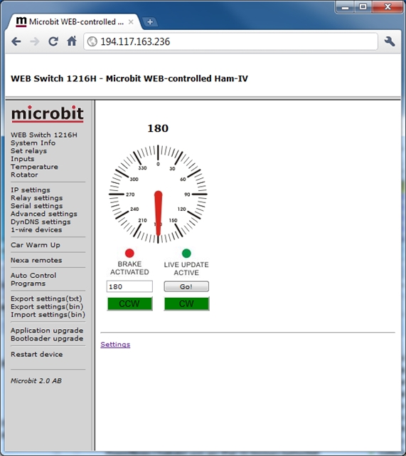
When the setup is done you only need the rotator window in the future. It’s quite Intuitive I think.
You can turn the antenna CW or CCW manually by pressing and hold the CW or CCW buttons. The buttons vill change from green to red when the rotator is turning the antenna.
You can also set a direction by entering the wanted direction in the box and press the “Go!” button. The Rotator will the go to the right direction automatically. You can stop the rotation by pressing the “Stop” button
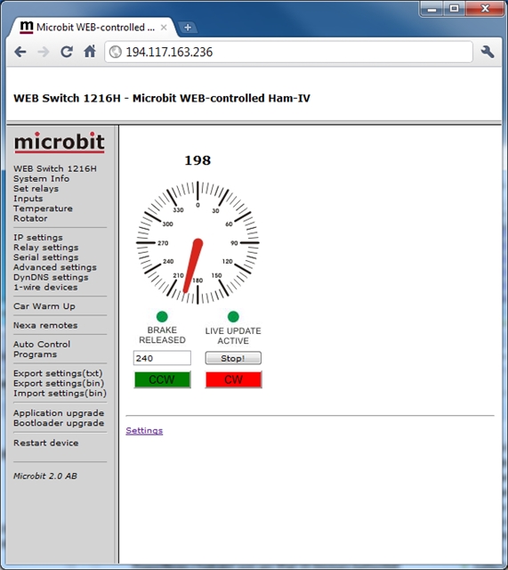
The “Brake Released/Activated” LED will indicate when the brake is released, It will be released a moment before the rotation is started and activated a few seconds after the rotation has stopped.
The “Live Update Active/Not Active” will indicate if the window is showing Live values, It will change to “Live Not Active” after about 30 seconds of no activity.
Have fun……


