


Description
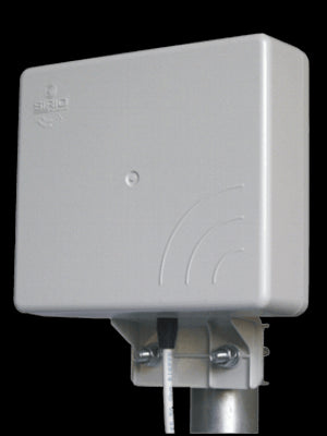
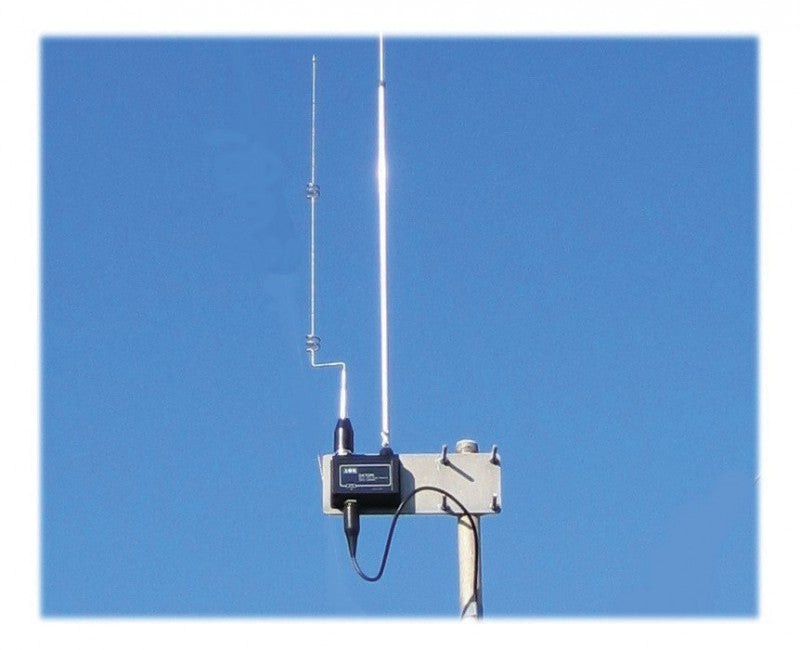
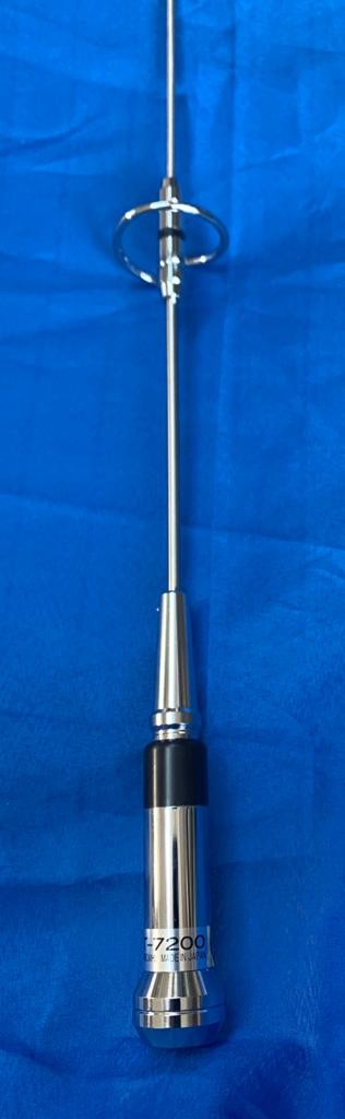
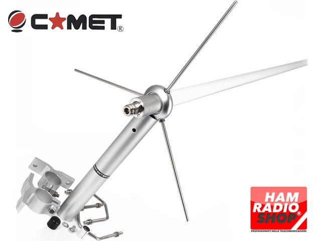
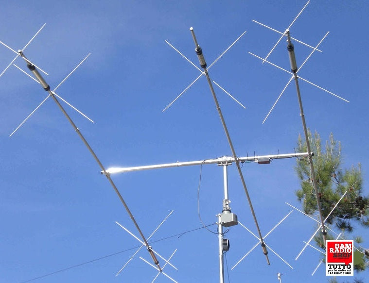
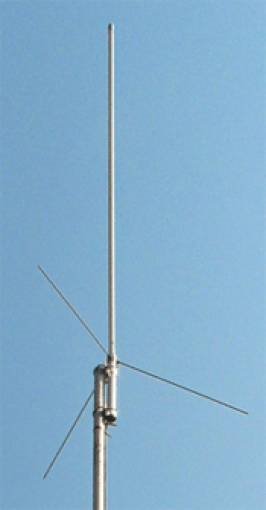
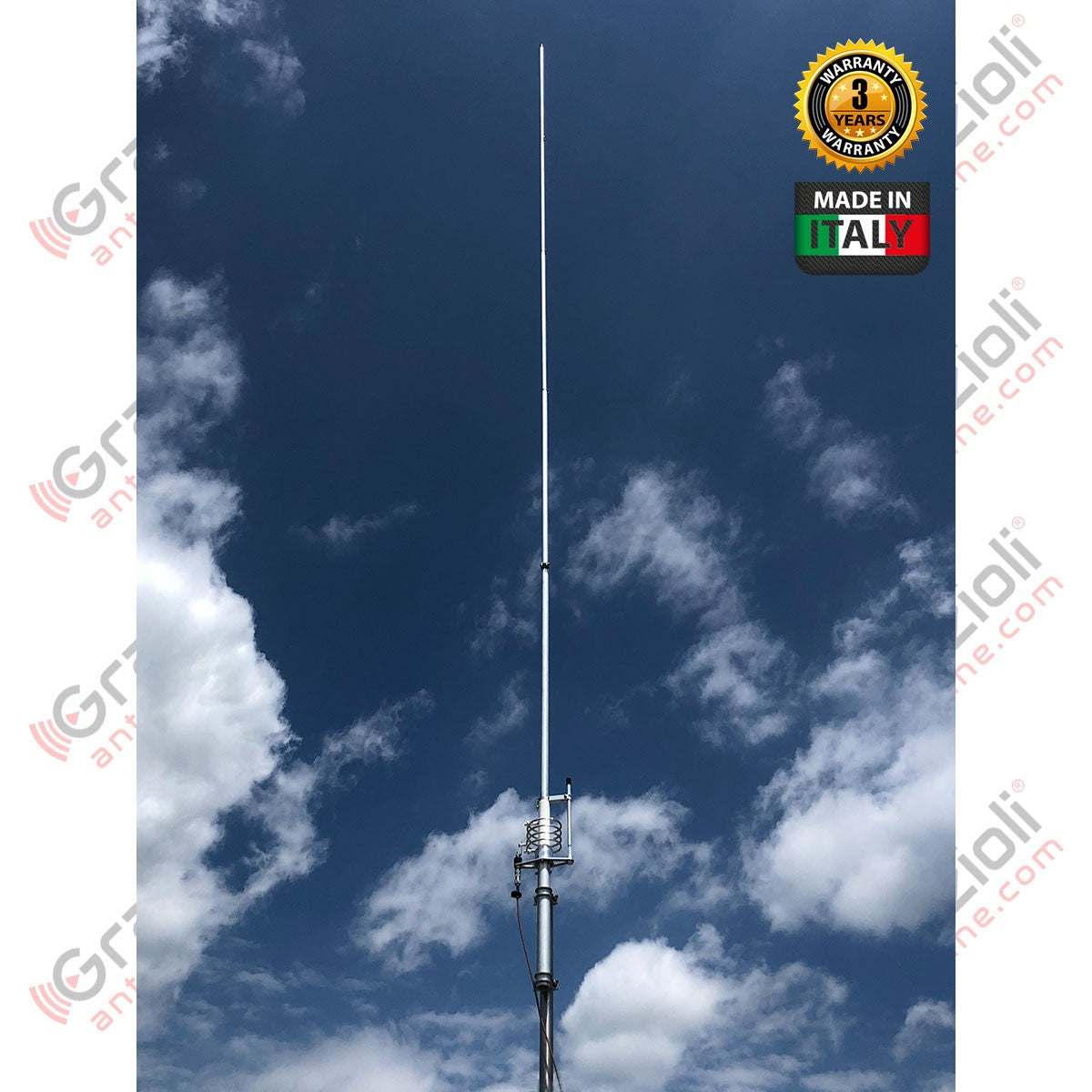
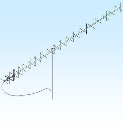
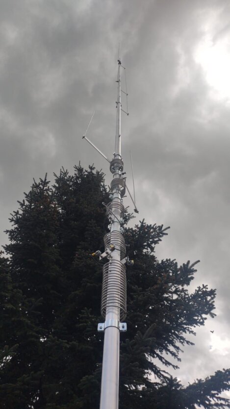
1/2 ? vertical antenna fed at the base, tunable from 26 to 30 MHz by adjusting the whip length, and fine tuning at the base via a high voltage (40KV) variable capacitor insulated with PTFE.
Extremely robust construction in AW6063-T66 aluminum alloy and parts machined from solid with CNC.
Supplied with quality INOX 304 and 316 screws for long rust-free service.
High applicable input power, up to 3Kw continuous All-mode.
Detailed assembly manual and serial number identifying the production batch and manufacturing data.
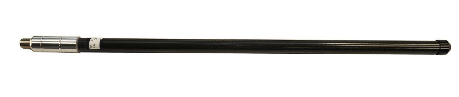
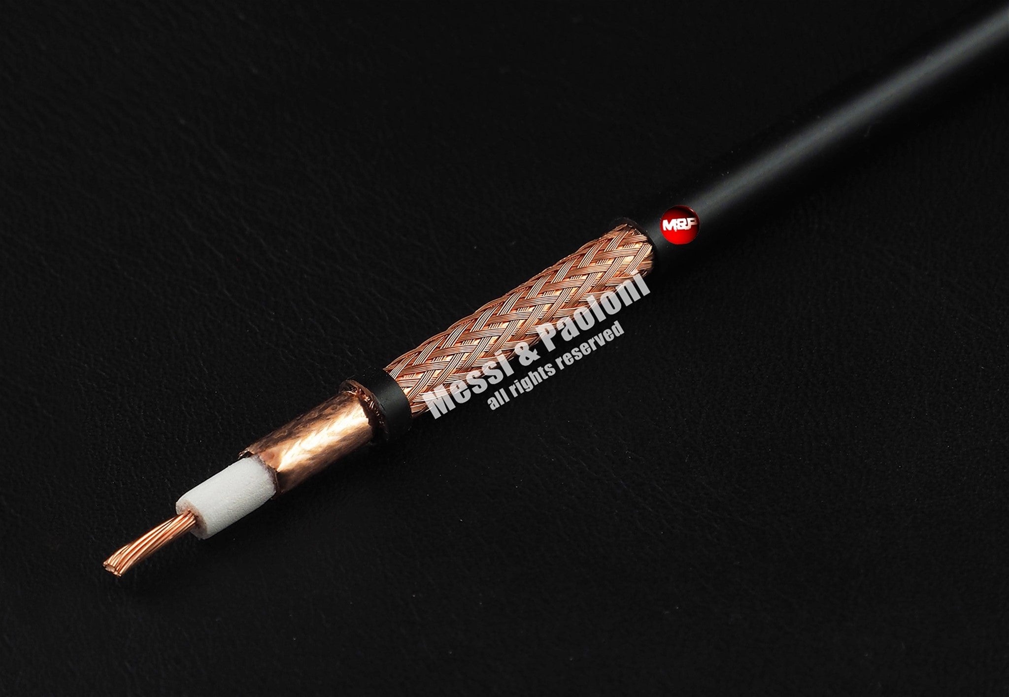
For our tubes, we have used the best alloy available for antenna construction, the AW6063-T66 aluminum, magnesium, and silicon alloy, tempered to T-66 state, which gives the whip exceptional strength. It is manufactured by extrusion and then cold-drawn. Our tubes are extremely precise in both diameters, and also in wall thickness, allowing for a precise coupling with less "play" between the tubes.
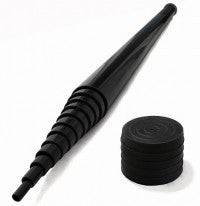
The sections of the vertical whip are distributed as follows, starting from the bottom:
Anchoring tube D.42×2
1st stage above the coil D.29×1.5
2nd stage D.25.5×1.5
3rd stage D.22×1.25
4th stage D.19×1.25
5th stage D.16×1.25
Insulator made of white fiberglass D.38 with a thickness of 4.2mm.
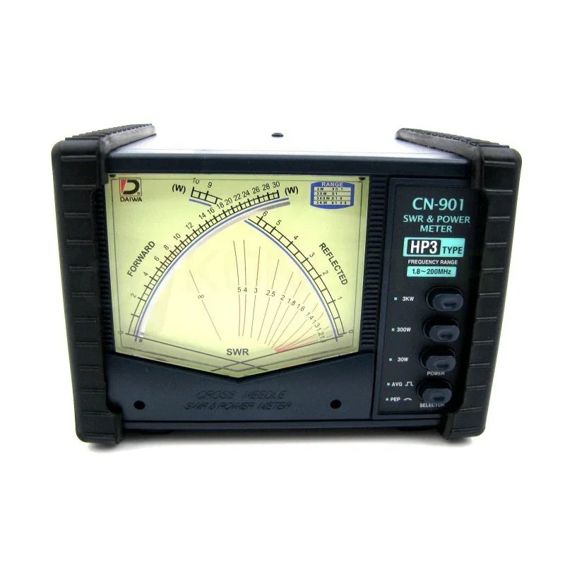
Because an antenna that accepts high power is a more efficient antenna, otherwise it would tend to heat up due to the Joule effect and dissipate a significant part of the applied RF power as heat, which happens with most competing products, but which unfortunately users cannot test due to lack of adequate equipment and instrumentation.
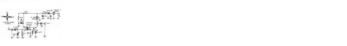
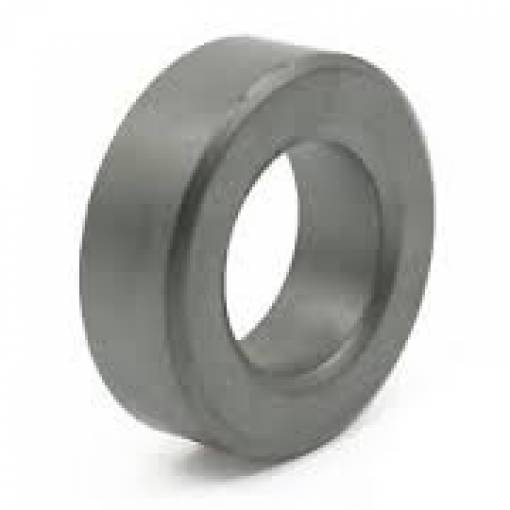
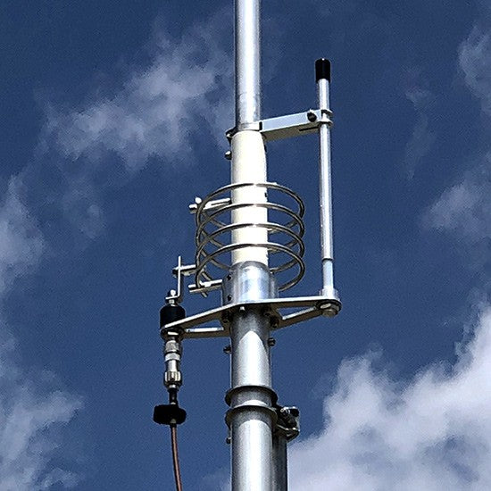
The High "Q" L-C Matching Circuit
For this product, we have created a special parallel L-C circuit to adapt the high impedance that these types of antennas present when fed at the base. The high "Q" coil is generously sized, air-suspended without metal cores, with widely spaced turns. The coaxial variable capacitor (similar to a Gamma Match) placed next to the coil is made with PTFE insulation. It is able to withstand extremely high voltages exceeding 40 KV, is not affected by ambient temperature, rain or humidity, and does not heat up when subjected to high powers. In addition, it allows for easy and convenient tuning at the base of the antenna.
During the development of the matching circuit, we had to carefully adjust both the inductance (L) and the capacitance (C) to obtain a truly efficient, reliable, and problem-free circuit. All these measures result in high efficiency and the ability to withstand RF powers up to 3Kw continuous in all modes.
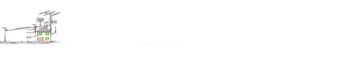
Furthermore, the coil is directly connected to the ground in direct current (DC-Ground), which significantly reduces atmospheric and impulse noise.

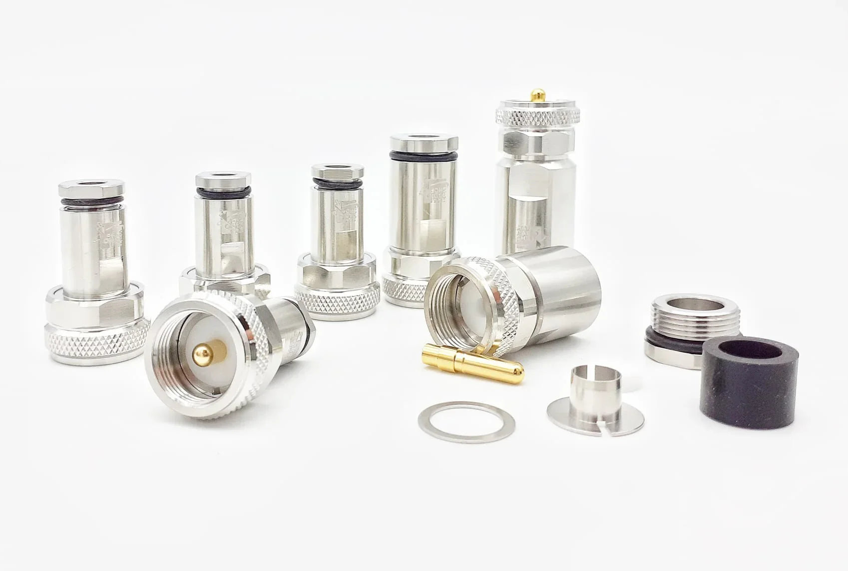
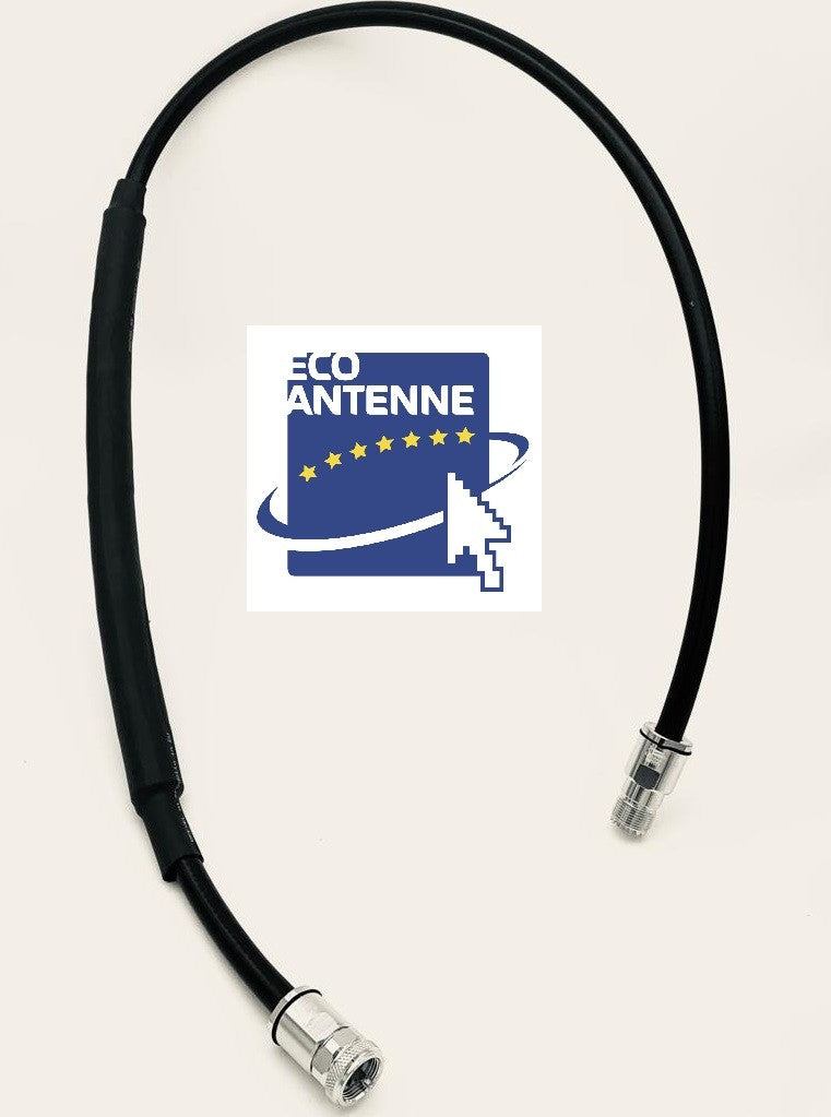
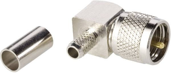
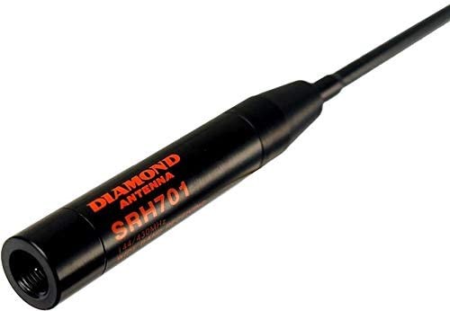
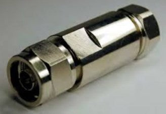
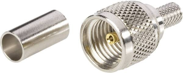
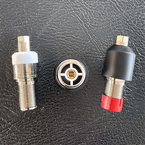
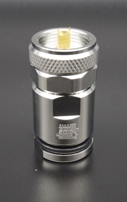
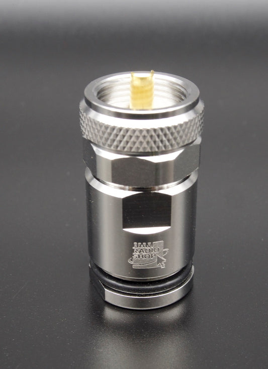
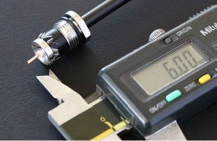
The UHF Connector
The HW10V connector is not a commercial SO-239 type as used by most manufacturers. The connector was designed and manufactured directly by us, it has a real impedance of 50 Ohms and can be used up to 500MHz. We have created a reliable connector capable of handling the transmission of 5Kw continuous CW at 30MHz and more than 3Kw at 50MHz.
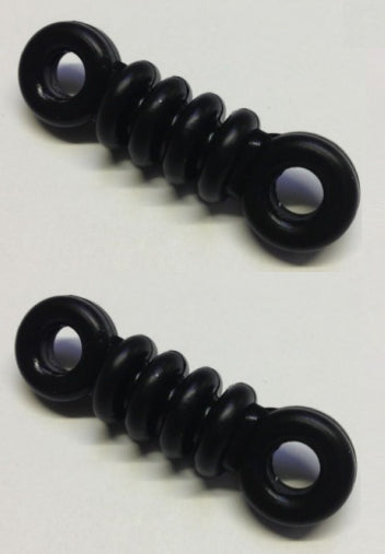
The body is made of nickel-plated CW614N brass, while the pin is 24K gold-plated to prevent oxidation and is equipped with a 4-fin insulator that maintains its centering and elasticity, preventing loss of contact.
The insulating part is made of PTFE, which is one of the best insulating materials due to its exceptional electrical properties (low dielectric constant and reduced loss factor) and thermal properties (operating temperature from -100° to +260°), and is protected by a special elastomer cap that prevents water and moisture infiltration.

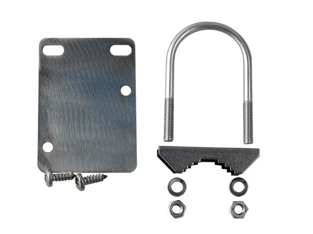
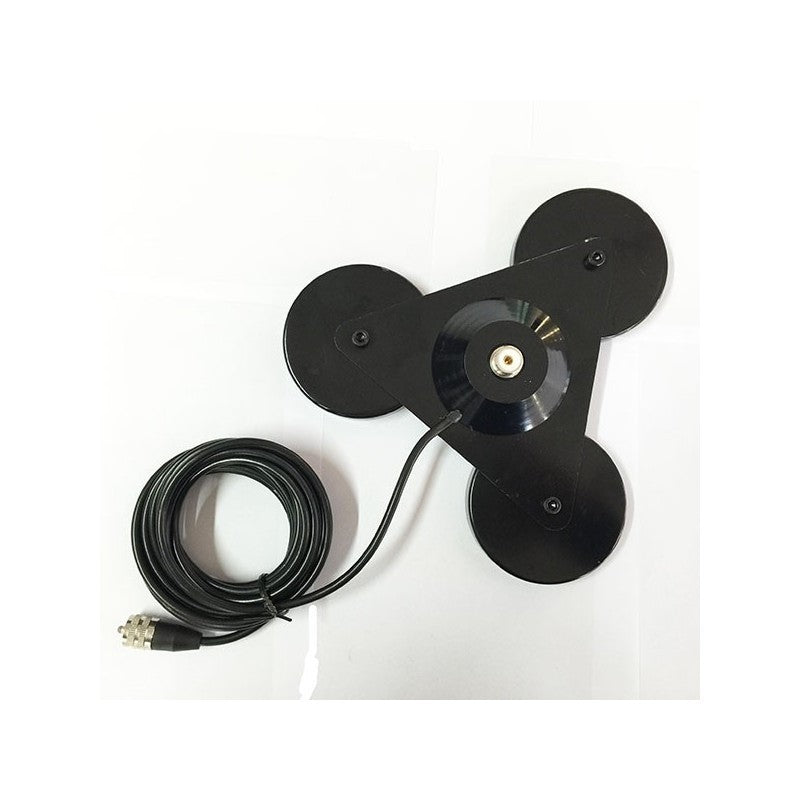
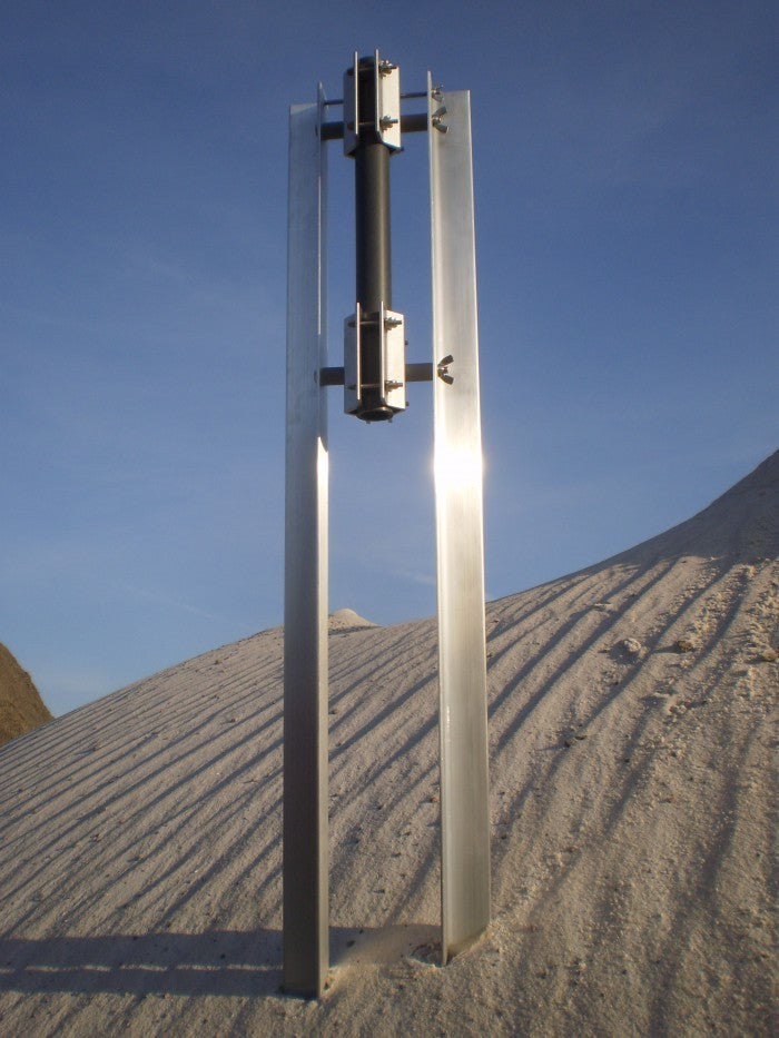
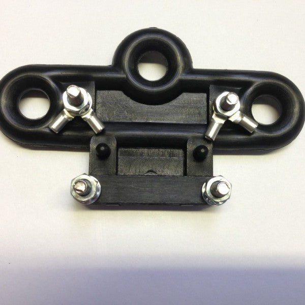
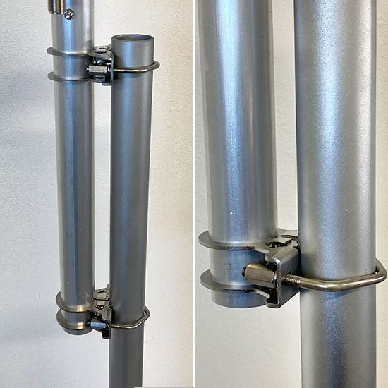
The Anchoring Bracket
Made of AISI304 stainless steel, 2.5 mm thick, it is fixed to the antenna tube using a clamp system, creating an extremely robust mechanical lock.
The mast attachment is made with M6 V-Bolt U-bolts in AISI304 and column nuts to facilitate tightening.


